
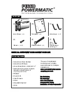

FRAME
DOOR
N
NB
B
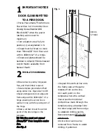
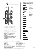
T
To
o e
en
nssu
urre
e cco
orrrre
ecctt o
op
pe
erra
attiio
on
n o
off
ccllo
osse
err tth
he
erre
e m
mu
usstt b
be
e a
a 3
3m
mm
m//
1
1
//
8
8
”
” g
ga
ap
p
b
be
ettw
we
ee
en
n tth
he
e ttw
wo
o ffiix
xiin
ng
g p
plla
atte
ess w
wh
he
en
n
tth
he
e d
do
oo
orr iiss iin
n tth
he
e ccllo
osse
ed
d p
po
ossiittiio
on
n..
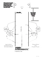
T
Th
he
esse
e iin
nssttrru
uccttiio
on
nss a
arre
e b
ba
asse
ed
d o
on
n tth
he
e
g
ga
ap
p b
be
ettw
we
ee
en
n d
do
oo
orr a
an
nd
d ffrra
am
me
e b
be
eiin
ng
g
3
3m
mm
m +
+
-- 1
1..0
0m
mm
m..
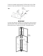
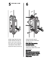
• Drill 4 x 28mm/1
1
/
8
” Ø holes x30mm/1
5
/
16
”
deep to accept frame plate assembly as
indicated on template.
• Drill 2 x 28mm/1
1
/
8
” Ø holes x5mm deep
to accept frame plate ends.
• Remove excess timber between drilled
holes to accommodate frame plate.
FRAME PREPARATION FOR
FRAME PLATE
3
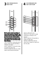
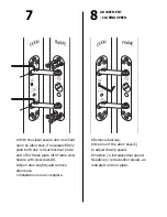
• Drill 4 x 26mm/1
1
/
16
” Ø x
185mm/7
5
/
16
” deep holes to accept
closer body as indicated on the
template.
• Drill 2 x 28mm/1
1
/
8
” Ø holes x5mm to
accept door plate ends.
• Remove excess timber between
drilled holes to accept the closer body
and door plate.
4
DOOR PREPARATION FOR
BODY & DOOR PLATE
FRAME
DRILL
TO
30mm/1
/
16
”
DEEP
5