


i08134372
Maintenance
Section
Refill
Capacities
Refill
Capacities
Lubrication
System
OEM
–
Original
Equipment
Manufacturer
The refill capacities for the engine crankcase reflect
the approximate capacity of the crankcase or sump
plus standard oil filters. Auxiliary oil filter systems will
require extra oil. Refer to the OEM specifications for
the capacity of the auxiliary oil filter. Refer to the
Operation and Maintenance Manual, “Maintenance
Section” for more information on Lubricant
Specifications.
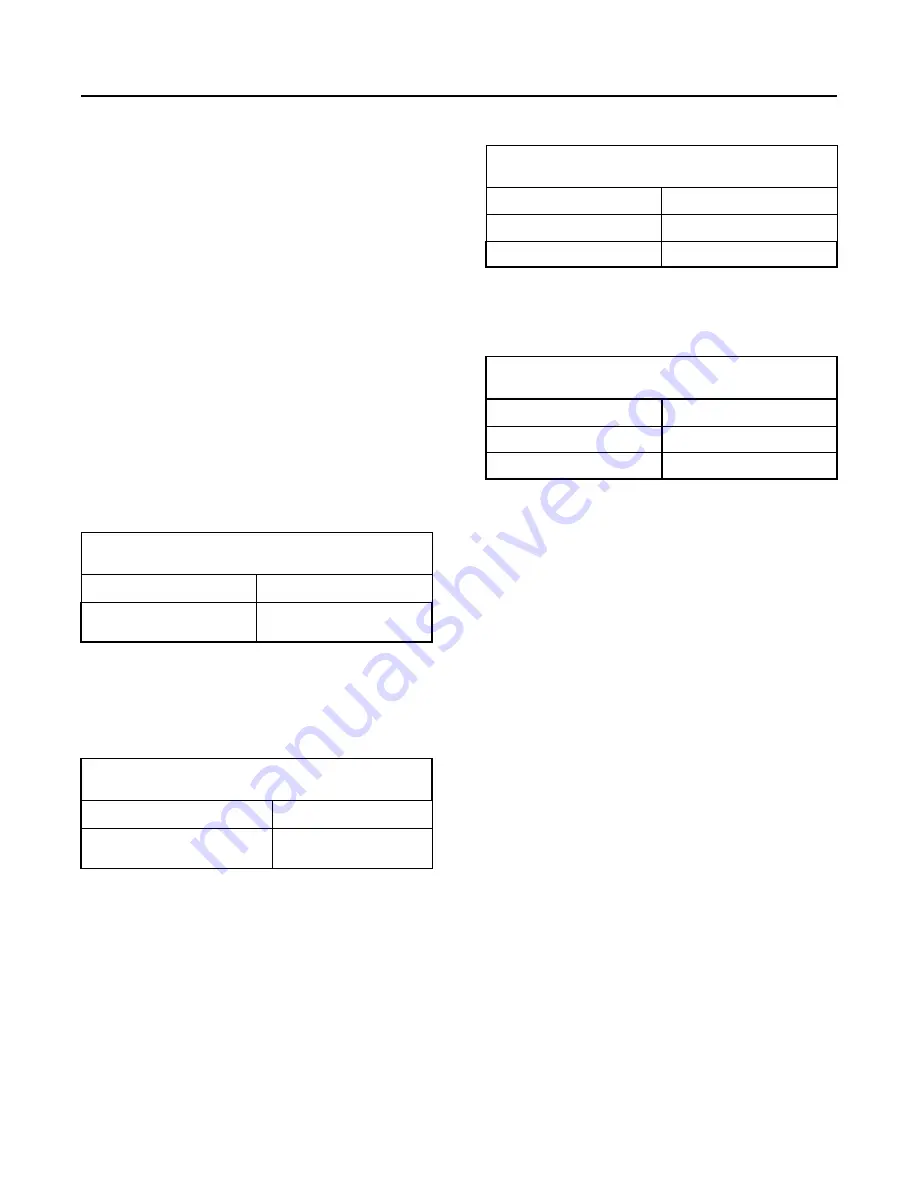
Table 3
904D-E28T Industrial Engine
Refill Capacities
Compartment or System
Capacity
Crankcase Oil Sump
7.5 to 8.8 L
(1.98150 to 2.32496 US gal)
(1)
These values are the approximate capacities for the crankcase
oil sump which includes the standard factory installed oil filters.
Engines with auxiliary oil filters will require extra oil. Refer to
the OEM specifications for the capacity of the auxiliary oil filter.
The design of the oil pan can change the oil capacity of the oil
pan.
Table 4
904D-E36TA Industrial Engine
Refill Capacities
Compartment or System
Capacity
Crankcase Oil Sump
8 to 10.6 L
(2.11360 to 2.80052 US gal)
(1)
These values are the approximate capacities for the crankcase
oil sump which includes the standard factory installed oil filters.
Engines with auxiliary oil filters will require extra oil. Refer to
the OEM specifications for the capacity of the auxiliary oil filter.
The design of the oil pan can change the oil capacity of the oil
pan.
Cooling System
Refer to the OEM specifications for the External
System capacity. This capacity information will be
needed to determine the amount of coolant/
antifreeze that is required for the Total Cooling
System.
Table 5
904D-E28T Industrial Engine
Refill Capacities
Compartment or System
Capacity
Engine Only
3.9 L (1.03038 US gal)
External System Per OEM
(1)
The External System includes a radiator or an expansion tank
with the following components: heat exchanger and piping. Re-
fer to the OEM specifications. Enter the value for the capacity
of the External System in this row.
Table 6
904D-E36TA Industrial Engine
Refill Capacities
Compartment or System
Capacity
Engine Only
4.3 L (1.136 US gal)
External System Per OEM
(1)
The External System includes a radiator or an expansion tank
with the following components: heat exchanger and piping. Re-
fer to the OEM specifications. Enter the value for the capacity
of the External System in this row.
i07794074
Fluid
Recommendations
(General
Fuel
Information)
•
Glossary
• ISO International Standards Organization
• ASTM American Society for Testing and Materials
• HFRR High Frequency Reciprocating Rig for
Lubricity testing of diesel fuels
• FAME Fatty Acid Methyl Esters
• CFR Co-ordinating Fuel Research
• LSD Low Sulfur Diesel
• ULSD Ultra Low Sulfur Diesel
• RME Rape Methyl Ester
• SME Soy Methyl Ester
• EPA Environmental Protection Agency of the
United States
M0108133-04
55