Perkins 2806C-E18TA Operation And Maintenance Manual Download Page 8

• Do not attempt any repairs or any adjustments to

the engine while the engine is operating.

• Do not attempt any repairs that are not

understood. Use the proper tools. Replace any
equipment that is damaged or repair the
equipment.

• For initial start-up of a new engine or for starting

an engine that has been serviced, make
provisions to stop the engine if an overspeed
occurs. The stopping of the engine may be
accomplished by shutting off the fuel supply and/
or the air supply to the engine. Ensure that only
the fuel supply line is shut off. Ensure that the fuel
return line is open.

• Start the engine from the operators station (cab).

Never short across the starting motor terminals or
the batteries. This action could bypass the engine
neutral start system and/or the electrical system
could be damaged.

Engine exhaust contains products of combustion
which may be harmful to your health. Always start the
engine and operate the engine in a well ventilated
area. If the engine is in an enclosed area, vent the
engine exhaust to the outside.

Cautiously remove the following parts. To help
prevent spraying or splashing of pressurized fluids,
hold a rag over the part that is being removed.

• Filler caps

• Grease fittings

• Pressure taps

• Breathers

• Drain plugs

Use caution when cover plates are removed.
Gradually loosen, but do not remove the last two
bolts or nuts that are located at opposite ends of the
cover plate or the device. Before removing the last
two bolts or nuts, pry the cover loose in order to
relieve any spring pressure or other pressure.
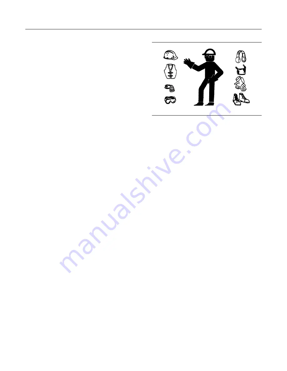
Illustration 6

g00702020

• Wear a hard hat, protective glasses, and other

protective equipment, as required.

• When work is performed around an engine that is

operating, wear protective devices for ears in
order to help prevent damage to hearing.

• Do not wear loose clothing or jewelry that can

snag on controls or on other parts of the engine.

• Ensure that all protective guards and all covers

are secured in place on the engine.

• Never put maintenance fluids into glass

containers. Glass containers can break.

• Use all cleaning solutions with care.

• Report all necessary repairs.

Unless other instructions are provided, perform
the maintenance under the following conditions:

• The engine is stopped. Ensure that the engine

cannot be started.

• Disconnect the batteries when maintenance is

performed or when the electrical system is
serviced. Disconnect the battery ground leads.
Tape the leads in order to help prevent sparks.

• Do not attempt any repairs that are not

understood. Use the proper tools. Replace any
equipment that is damaged or repair the
equipment.

Pressurized Air and Water

Pressurized air and/or water can cause debris and/or

hot water to be blown out. This action could result in

personal injury.

When pressurized air and/or pressurized water is
used for cleaning, wear protective clothing, protective
shoes, and eye protection. Eye protection includes
goggles or a protective face shield.

8

SEBU9074-01

Safety Section
General Hazard Information

Summary of Contents for 2806C-E18TA

Page 1: ...Operation and Maintenance Manual 2806C E18TA and 2806D E18TA Industrial Engine JG1 Engine SEBU9074 01 en us January 2017...

Page 2: ...ing explains the hazard and can be either written or pictorially presented Operations that may cause product damage are identified by NOTICE labels on the product and in this publication Perkins canno...

Page 3: ...ronics 15 Product Information Section General Information 16 Product Identification Information 22 Operation Section Lifting and Storage 24 Features and Controls 28 Engine Diagnostics 34 Engine Starti...

Page 4: ...d to detailed instructions that follow Recommended service should be performed at the appropriate intervals as indicated in the Maintenance Interval Schedule The actual operating environment of the en...

Page 5: ...water and soap to clean the safety messages Do not use solvents gasoline or other harsh chemicals Solvents gasoline or harsh chemicals could loosen the adhesive that secures the safety messages The s...

Page 6: ...2806D E18TA Safety Label Positions Illustration 2 g03856817 Illustration 3 g03857446 6 SEBU9074 01 Safety Section Safety Messages...

Page 7: ...ctive glasses and other protective equipment as required When work is performed around an engine that is operating wear protective devices for ears in order to help prevent damage to hearing Do not we...

Page 8: ...he cover plate or the device Before removing the last two bolts or nuts pry the cover loose in order to relieve any spring pressure or other pressure Illustration 6 g00702020 Wear a hard hat protectiv...

Page 9: ...ing Fluid Spillage Care must be taken to ensure that fluids are contained during performance of inspection maintenance testing adjusting and repair of the product Be prepared to collect the fluid with...

Page 10: ...ands lining material clutch plates and some gaskets The asbestos that is used in these components is usually bound in a resin or sealed in some way Normal handling is not hazardous unless airborne dus...

Page 11: ...battery is an electrolyte Electrolyte is an acid that can cause personal injury Do not allow electrolyte to contact the skin or the eyes Do not smoke while checking the battery electrolyte levels Bat...

Page 12: ...The filter housings must be tightened to the correct torque Refer to the Disassembly and Assembly manual for more information Illustration 11 g00704059 Use caution when you are refueling an engine Do...

Page 13: ...ver attempt adjustments while the engine is running Stay clear of all rotating parts and of all moving parts Leave the guards in place until maintenance is performed After the maintenance is performed...

Page 14: ...e engine in a ventilated area If the engine is started in an enclosed area vent the engine exhaust to the outside Note The engine may be equipped with a device for cold starting If the engine will be...

Page 15: ...d or engine damage This engine has a comprehensive programmable Engine Monitoring System The Electronic Control Module ECM will monitor the engine operating conditions If any of the engine parameters...

Page 16: ...pear different from the illustrations 2806C Illustration 13 g06095280 Typical example 1 Front lifting eye 2 Breather outlet hose 3 Rear lifting eye 4 Air cleaner 5 Electronic control module 6 Starting...

Page 17: ...13 Alternator 14 Alternator belt 15 Fan belts 16 Damper 17 Coolant outlet 18 Oil drain plug 19 Oil gauge Dipstick 20 Oil filter 21 Oil cooler 22 Engine block heater 23 Oil filler 24 Turbochargers SEBU...

Page 18: ...ver 5 Turbochargers 6 Engine rear lifting eye 7 Air filter 8 Electronic Control Module ECM 9 Oil drain plug 10 Breather fume outlet hose 11 Secondary fuel filter and priming pump 12 Primary fuel filte...

Page 19: ...6D E18TAindustrial engines have the following characteristics Four stroke cycle Mechanically actuated electronically controlled fuel injection system Turbocharged Air to air charged cooled Engine Spec...

Page 20: ...nd the pumping are done under high pressure High injection pressures help to reduce fuel consumption and emissions The use of this type of unit injector provides total electronic control of injection...

Page 21: ...l consumption of the engine over a time Reduced hours of operation at full throttle and or operating at reduced throttle settings result in a lower average power demand Reduced hours of operation will...

Page 22: ...injectors Illustration 19 g03857570 2 Serial number plate for the 2806D engine The engine serial number plate for the 2806D is on the right side of the engine block next to the front oil filter Illus...

Page 23: ...bel is located on the engine oil cooler i06216646 Reference Information Information for the following items may be needed to order parts Locate the information for your engine Record the information i...

Page 24: ...thin product lifting before any lifting is attempted Ensure that the correct set of lifting eyes for the assembly to be lifted have been selected Use a hoist to remove heavy components Use an adjustab...

Page 25: ...o the inlet by removing the plug on the air inlet elbow on the left side of the engine The minimum application rate for the VCI oil mixture is 5 5 mL per L 3 oz per 1000 cu in of engine displacement 7...

Page 26: ...cover is secure The cover should be loose enough to allow air to circulate around the engine in order to prevent damage from condensation 15 Attach a tag with the storage date to the engine 16 Remove...

Page 27: ...ition of all rubber hoses Replace any worn hoses Replace any damaged hoses 10 Before start up test the cooling system for a 3 percent to a 6 percent concentration of coolant conditioner Add liquid coo...

Page 28: ...Warning alarm will be set to a factory default in production The electronic service tool may be used to alter the trip point for a Warning within predefined limits Action Alert The Action Alert inform...

Page 29: ...odule can be powered down by isolating the power supply to the electronic control module Note The ECM cannot be reset by using the Reset input until the engine has stopped Diagnostic If there is a fau...

Page 30: ...Intake manifold pressure sensor 3 Fuel temperature sensor 4 Intake manifold temperature sensor 5 Electronic Control Module ECM 6 Oil pressure sensor 7 Atmospheric pressure sensor 8 Crankshaft speed t...

Page 31: ...Illustration 26 g06095652 9 Sender for cylinder block heater 10 Coolant temperature sensor 11 Cylinder block heater if equipped SEBU9074 01 31 Operation Section Sensors and Electrical Components...

Page 32: ...manifold pressure sensor 3 Intake manifold temperature sensor 4 Fuel temperature sensor 5 Electronic Control Module ECM 6 Oil pressure sensor 7 Atmospheric pressure sensor 8 Crankshaft speed timing se...

Page 33: ...Illustration 28 g03858148 9 Coolant temperature sensor SEBU9074 01 33 Operation Section Sensors and Electrical Components...

Page 34: ...n active diagnostic code the code will be logged in the memory of the ECM The codes that have been logged by the ECM can be identified by the electronic service tool The active codes that have been lo...

Page 35: ...pped The operator should retrieve the logged fault codes and reference the appropriate information in order to identify the nature of the event The operator should log any observation that could have...

Page 36: ...ent the exhaust to the outside If there is a DO NOT OPERATE warning tag or similar attached to the start switch or the controls do not start the engine or move any controls Ensure that the areas aroun...

Page 37: ...flywheel is turning Do not start the engine under load If the engine fails to start within 30 seconds release the starter switch or button and wait two minutes to allow the starting motor to cool bef...

Page 38: ...of battery cables from a battery may cause an explosion which may result in in jury or death The connection and the disconnec tion of other electrical equipment may also cause an explosion which may...

Page 39: ...al Starting the Engine 5 Immediately after the engine is started disconnect the jump start cables in reverse order After jump starting the alternator may not be able to recharge batteries to full capa...

Page 40: ...gauges and check the equipment for proper operation Check the gauges and check the equipment frequently while the engine is operating under load i06217701 Fuel Conservation Practices The efficiency o...

Page 41: ...system when possible Keep cooling system components clean and keep cooling system components in good repair Never operate the engine without a water temperature regulator All of these items will help...

Page 42: ...e temperature at which waxes naturally found in the diesel fuel begin to form crystals The cloud point of the fuel must be below lowest ambient temperature to prevent filters from plugging Cold Filter...

Page 43: ...er should also help to prevent overheating of the fuel High fuel temperatures reduce engine performance and the availability of engine power Choose a fuel heater with a large heating surface The fuel...

Page 44: ...tood Use the following general guidelines in order to stop the engine 1 Remove the load from the engine so that the engine has no more than 30 power 2 Run the engine for at least 3 minutes 3 After the...

Page 45: ...cooling system the total cooling system capacity must be known The capacity of the total cooling system will vary The capacity will depend on the size of the radiator capacity Table 3 should be comple...

Page 46: ...quired oil viscosity for starting a cold engine Refer to illustration 32 maximum temperature in order to select the oil viscosity for engine operation at the highest ambient temperature that is antici...

Page 47: ...tion NOTICE Never add coolant to an overheated engine Engine damage could result Allow the engine to cool first NOTICE If the engine is to be stored in or shipped to an area with below freezing temper...

Page 48: ...rkins recommends a 1 1 mixture of a water glycol solution Note Use a mixture that will provide protection against the lowest ambient temperature Note 100 percent pure glycol will freeze at a temperatu...

Page 49: ...s in order to provide superior corrosion protection for all metals in engine cooling systems ELC is available in a premixed cooling solution with distilled water ELC is a 1 1 mixture The Premixed ELC...

Page 50: ...ther products reduces the effective ness of the ELC and shortens the ELC service life Use only Perkins Products for premixed or concen trate coolants Failure to follow these recommenda tions can resul...

Page 51: ...necessary Table 11 Equation For Adding The SCA To The Heavy Duty Coolant For Maintenance V 0 014 X V is the total volume of the cooling system X is the amount of SCA that is required Table 12 is an ex...

Page 52: ...stated in table 13 NOTICE The footnotes are a key part of the Perkins Specifica tion for Distillate Diesel Fuel Table Read ALL of the footnotes Table 13 Perkins Specification for Distillate Diesel Fue...

Page 53: ...ents at 40 C 104 F of either the ASTM D445 test method or the ISO 3104 test method If a fuel with a low viscosity is used cooling of the fuel may be required to maintain 1 4 cSt or greater viscosity a...

Page 54: ...ter fuels are acceptable but these fuels will not produce the rated power Sulfur The level of sulfur is governed by emissions legislations Regional regulation national regulations or international reg...

Page 55: ...e when used with ap propriate lubricity additive and must meet minimum requirements that are listed in table 13 The lubricity of these fuels must not exceed wear scar diameter of 0 46 mm 0 01811 inch...

Page 56: ...es This cleaning of the fuel system can prematurely block of the fuel filters Perkins recommends that after the initial usage of B20 biodiesel blended fuel the fuel filters must be replaced at 50 hour...

Page 57: ...ecommends that seasonally operated engines have the fuel systems including fuel tanks flashed with conventional diesel fuel before prolonged shutdown periods An example of an application that should s...

Page 58: ...basis with no adverse impact on engine or fuel system durability Detailed instructions on the rate of which the fuel cleaner must be use are on the container Perkins Diesel Fuel Conditioner Perkins D...

Page 59: ...commended cleanliness level Install desiccant type breathers of 4 m or less absolute efficiency with the ability to remove water on bulk storage tanks Follow proper practices of fuel transportation Fi...

Page 60: ...pressure from the lubricating system turn off the engine i06221218 Welding on Engines with Electronic Controls NOTICE Because the strength of the frame may decrease some manufacturers do not recommen...

Page 61: ...are located between the welder ground and the weld current flow from the welder could severely damage the component 6 Protect the wiring harness from welding debris and spatter 7 Use standard welding...

Page 62: ...uipment is cleaned regularly Mud dirt and dust can encase components Maintenance can be very difficult The buildup can contain corrosive chemicals Buildup Compounds elements corrosive chemicals and sa...

Page 63: ...ngine Oil Sample Obtain 79 Engine Oil and Filter Change 79 Every 500 Service Hours or 1 Year Battery Electrolyte Level Check 65 Cooling System Supplemental Coolant Additive SCA Test Add 72 Fuel System...

Page 64: ...air compressor exhausts all personnel should be at a safe distance away from the air compressor All personnel should also stay clear of the air compressor when the engine is operating and the air comp...

Page 65: ...used battery 6 Install the new battery Note Before the cables are connected ensure that the engine start switch is OFF 7 Connect the cable from the starting motor to the POSITIVE battery terminal 8 C...

Page 66: ...ceed with necessary system repairs 8 In order to connect the battery connect the positive connection before the negative connector i06757654 Belts Inspect Adjust Replace Inspection To maximize the eng...

Page 67: ...m 34 lb ft Tighten nut and bolt 3 to a torque of 70 N m 51 lb ft Alternator Belt Adjustment 2806D Illustration 36 g06109400 2806D engine view 1 Remove the belt guard refer to OEM for the correct proc...

Page 68: ...system and flush the cooling system before the recommended maintenance interval if the following conditions exist The engine overheats frequently Foaming is observed The oil has entered the cooling sy...

Page 69: ...ant level Maintain the coolant level within 13 mm 0 5 inch below the bottom of the pipe for filling Maintain the coolant level within 13 mm 0 5 inch to the proper level on the sight glass 4 Clean the...

Page 70: ...e water to drain Flush the cooling system with clean water Close the drain valve Fill NOTICE Fill the cooling system no faster than 19 L 5 US gal per minute to avoid air locks 1 Fill the cooling syste...

Page 71: ...the cooling system filler cap and check the condition of the filler cap gaskets Replace the cooling system filler cap if the filler cap gaskets are damaged Reinstall the cooling system filler cap 4 In...

Page 72: ...e a Coolant Conditioner Test Kit in order to check the concentration of the SCA Add the SCA If Necessary NOTICE Do not exceed the recommended amount of supple mental coolant additive concentration Exc...

Page 73: ...with an electronic unit injector which is improperly adjusted may reduce engine efficiency This reduced efficiency may result in excessive fuel usage and or shortened engine component life Note Only...

Page 74: ...irt and debris as needed Operating in dirty conditions may require more frequent service of the air cleaner element The air cleaner element should be replaced at least one time per year This replaceme...

Page 75: ...the outer cover Discard any damaged air cleaner element Two methods may be used in order to clean the primary air cleaner element pressurized air Vacuum cleaning Pressurized Air Personal injury can re...

Page 76: ...and Maintenance Manual Engine Air Precleaner Check Clean procedure if equipped before performing the following procedure NOTICE Never run the engine without an air cleaner element installed Never run...

Page 77: ...movement of the service indicator core when the engine is run at full load speed The core should latch approximately at the greatest vacuum that is attained If the service indicator does not reset ea...

Page 78: ...gine Mounts Inspect Note The engine mounts may not have been supplied by Perkins Refer to the OEM information for further information on the engine mounts and the correct bolt torque Inspect the engin...

Page 79: ...nclude an oil sampling valve as an option The oil sampling valve if equipped is included in order to regularly sample the engine lubricating oil The oil sampling valve is positioned on the oil filter...

Page 80: ...s equipped with a drain valve turn the drain valve knob counterclockwise to drain the oil After the oil has drained turn the drain valve knob clockwise to close the drain valve If the engine is not eq...

Page 81: ...nd could be contaminated Contaminated oil can cause accelerated wear to en gine components 4 Install the new oil filters 3 Spin on the oil filter until the O rings contacts the sealing surfaces 2 Then...

Page 82: ...order to help provide maximum engine life NOTICE Only qualified service personel should perform this maintenance Refer to the Service Manual or your au thorized Perkins dealer or your Perkins distribu...

Page 83: ...759816 Fuel System Prime Fuel leaked or spilled onto hot surfaces or electri cal components can cause a fire To help prevent possible injury turn the start switch off when changing fuel filters or wat...

Page 84: ...riming pump handle several times until strong pressure is felt 5 When strong pressure can be felt press in the fuel priming pump handle 1 and lock the handle into the fuel pump body 2 To lock the hand...

Page 85: ...econdary fuel filter The element should be changed regularly If a vacuum gauge is installed the primary filter water separator should be changed at 50 to 70 kPa 15 to 20 inches Hg Illustration 55 g061...

Page 86: ...onto the fuel filter base 1 and tighten to a torque of 80 N m 59 lb ft Inspect the O ring seal Not Shown on drain plug 3 for wear or damage replace if necessary Install drain plug 3 into filter housi...

Page 87: ...ry Filter Replace 10 Dispose of the fluid and old filter in accordance with local regulations i06761567 Fuel System Primary Filter Water Separator Drain Fuel leaked or spilled onto hot surfaces or ele...

Page 88: ...spilled onto hot surfaces or electri cal components can cause a fire To help prevent possible injury turn the start switch off when changing fuel filters or water separator elements Clean up fuel spil...

Page 89: ...alve 3 3 Remove filter housing assembly 2 from filter base 1 Illustration 65 g06110975 Typical example 4 Remove filter element 4 from filter housing 2 and discard the old filter element Remove O ring...

Page 90: ...fore the fuel filter is removed After the engine has stopped wait for 1 to 5 minutes until the fuel pressure has lowered Use a suitable container to collect any fuel that may spill 2 Turn the fuel sup...

Page 91: ...iment from the fuel tank Fill the fuel tank after operating the engine in order to drive out moist air This will help prevent condensation Do not fill the tank to the top The fuel expands as the fuel...

Page 92: ...Cracking Softness Loose clamps Replace hoses that are cracked or soft Tighten any loose clamps Check for the following conditions End fittings that are damaged or leaking Outer covering that is chafe...

Page 93: ...d Check that connections and hoses are secure check for leaks If parts are to be removed or tightened refer to the Disassembly and Assembly manual for more information i05971077 Overhaul Consideration...

Page 94: ...2 Starting Motor Inspect Perkins recommends a scheduled inspection of the starting motor If the starting motor fails the engine may not start in an emergency situation Check the starting motor for pro...

Page 95: ...and for worn wires or frayed wires Inspect the ground strap for a good connection and for good condition Inspect the ECM to the cylinder head ground strap for a good connection and for good condition...

Page 96: ...New non road diesel engines including Tier 1 and Tier 2 marine propulsion engines 37 kW and Tier 1 through Tier 4 marine auxiliary engines 37 kW but excluding locomotive and other marine engines opera...

Page 97: ...ting cost Records should be kept for the following items Fuel Consumption A record of fuel consumption is essential in order to determine when the load sensitive components should be inspected or repa...

Page 98: ...intenance Log Table 15 Engine Model Customer Identifier Serial Number Arrangement Number Service Hours Quantity Of Fuel Service Item Date Authorization 98 SEBU9074 01 Reference Information Section Mai...

Page 99: ...vel of protection for your Perkins Engine Coverage can be extended to 2 years 1 000 hours right up to 10 year 40 000 You can buy an ESC at any time during standard warranty even the last day Each Perk...

Page 100: ...iagnostic Lamp 34 Driven Equipment Check 73 E Electrical System 14 Grounding Practices 15 Electronic Unit Injector Check Replace 73 Emissions Certification Film 23 Emissions Warranty Information 96 En...

Page 101: ...806D Water Separator Drain 88 Fuel System Secondary Filter Replace 88 2806C Secondary Fuel Filter 89 2806D Secondary Fuel Filter 90 Fuel Tank Water and Sediment Drain 91 Drain the Water and the Sedime...

Page 102: ...45 Coolant Refill Capacity 45 Lubricant Refill Capacity 45 S Safety Messages 5 2806C E18TA Safety Label Positions 5 2806D E18TA Safety Label Positions 6 Universal Warning 1 7 Safety Section 5 Self Di...

Page 103: ...aintenance Manual Delivery Date Product Information Model Product Identification Number Engine Serial Number Transmission Serial Number Generator Serial Number Attachment Serial Numbers Attachment Inf...

Page 104: ...2017 Perkins Engines Compony Limited All Rights Reserved...

Reviews: