Assembly Step
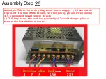
26
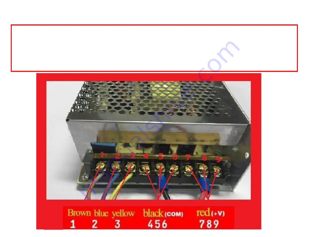
Attention:This is the wiring diagram of power supply. 1,2,3 seperately
represent the line offire(brown),Zero line(blue), ground wire (yellow).
4,5,6 represent negative pole (black)
(-);7,8,9represent the positive pole(red)(+).Toavoid danger, please
assure the installation is correct .
Summary of Contents for A8-W5
Page 1: ...A8 W53DPrinterInstallationGuide Perfect Office ...
Page 3: ...A8 W5 assembly parts list 1 ...
Page 4: ...A8 W5 assembly parts list 2 ...
Page 5: ...A8 W5 assembly parts list 3 ...
Page 6: ...A8 W5 assembly parts list 4 ...
Page 7: ...A8 W5 assembly parts list 5 ...
Page 8: ...A8 W5 assembly parts list 6 Please check printer parts quantity when you receiveit ...
Page 9: ...Name of each printer part ...
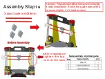
Page 10: ...Step1 Assembly Step1 Pleasebeawarethescrewholesisin red circles ...
Page 11: ...Assembly Step2 Pleasebeawarethescrew holesisinblackcircles Step 2 ...
Page 13: ...Assembly Step4 Step 2 Step 3 ...
Page 14: ...Assembly Step5 ...
Page 15: ...Assembly Step6 Threaded rod 400mm ...
Page 16: ...YGuiderod380mm Assembly Step7 ...
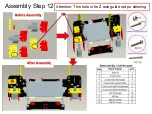
Page 21: ...Assembly Step 12 Attention This hole is for Z axis guide rod po sitioning ...
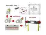
Page 22: ......
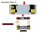
Page 23: ...Assembly Step14 ...
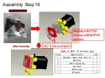
Page 27: ...Assembly Step18 M3 45screwholes Replace M3 20 screwswithM3 45 screws ...
Page 28: ...Assembly Step 19 ...
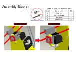
Page 30: ...Assembly Step 21 ...
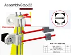
Page 31: ...AssemblyStep22 M3 20 ...
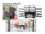
Page 33: ...Assembly Step24 M3 Nut ...
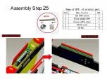
Page 34: ...Assembly Step25 ...
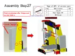
Page 36: ...Assembly Step27 Redcirclesstandfor thepower screw holes PowerSupply ...
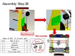
Page 37: ...Assembly Step28 Mainboard ...
Page 40: ......
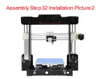
Page 41: ...AssemblyStep 32 InstallationPicture1 ...

