Assembly and Operation Manual
22
APPENDIX.
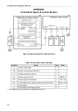
Connection layout of control devices
Fig. 8 Connection layout of control devices
Table 3 Connection layout elements
Symbol
Name
Q-ty
Note
A1 Control
unit
CU-02N
1
A2
Remote control panel H-06/4.100
1
A3
Turnstile housing T-04W-24
1
A4*
Wireless remote control
1 MSRF-4
A5*
Power supply of the turnstile
1
12V, 1.2
А
A6*
Power supply of the heating system with thermocontrol
1 24VAC, 2.5
А
1 Control
cable
1
2
Power cable of the heating system
1
*
This equipment is not included in a standard delivery set
.
Summary of Contents for TTR-04CW-24
Page 1: ......
Page 2: ...Electromechanical Tripod Turnstile PERCo TTR 04CW 24 Assembly and Operation Manual...
Page 24: ......
Page 26: ...www perco com export perco ru...


