background image

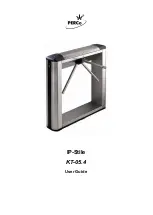
User Guide 

3  SAFETY MEASURES 

The IP-Stile is to be operated with observance of safety requirements mentioned in 
Section 7.2 of its Assembly & Operation Manual. 


Warning! 


  Do not use the IP-Stile under conditions that do not comply with the requirements 

of the operation documentation. 

  Do not use the IP-Stile at supply voltage that does not comply with the technical 

characteristics of the equipment. 

  Do not move through the IP-Stile passage area any objects with dimensions 

exceeding the width of the passageway. 

  Do not jerk and hit any elements of the IP-Stile so as to prevent their mechanical 

deformation. 

  Do not dismantle or adjust mechanisms ensuring operation of the IP-Stile. 

  Do not use substances that may cause mechanical damage or corrosion of 

the surfaces for cleaning the IP-Stile. 

4  POWER-UP 

At IP-Stile power-up follow this sequence of actions: 

1.  Make sure all connections are correct.  

2.  Make sure the barrier arms are in the home position (the passageway is blocked 

with a barrier arm).   

3.  Make sure the mechanical release lock is closed.  

4.  Connect the power supply to the mains with electric parameters as per its 

documentation.  

5.  Turn the power on.   


Attention! 

When the controller configuration is changed with the jumpers, the controller 
internal memory is automatically formatted. This procedure lasts for about 2 
minutes. After that the IP-Stile configuration should be transmitted to the controller 
by the Soft or Web-interface. 

6.  At the first powering the 

«Control» 

ACM is set for both directions. Yellow indicators 

(middle ones) of the indication modules are on and the red 

“Stop”

  indicator above 

the middle button on the RC-panel is on.  Both passage directions are blocked. 

7.  If the formatting has not been performed, the ACM and the indication, set for each 

passage direction before power failure, is saved.  

8.  The IP-Stile is ready for operation right after the power-up. The operator can send 

command for locking / unlocking of both passages from the RC-panel. In order to 
arrange passage with proximity cards the additional configuration is to be used. 

Summary of Contents for IP-Stile KT-05.4

Page 1: ...IP Stile KT 05 4 ASSEMBLY AND OPERATION MANUAL...

Page 2: ...IP Stile KT 05 4 User Guide...

Page 3: ...ety measures 6 4 Power up 6 5 Operation by RC panel 7 6 Operation as a part of an ACS 9 7 ACM controller events and states indication 10 8 Emergency actions 11 8 1 Emergency exit by use of anti panic...

Page 4: ...without permanent connection to the local network or a PC or as a part of PERCo Web security system All the registered events are logged in the nonvolatile memory of the IP Stile controller As a part...

Page 5: ...er arms adjusting points 7 mechanical release lock 8 indication module 9 front covers with readers 10 turnstile housing side cover 11 turnstile housing side cover lock 12 RC panel 13 RC panel cable No...

Page 6: ...module 2 2 RC panel The RC panel is designed as a small desktop device with a shock proof ABS plastic case and is intended for setting and indicating operating modes when the turnstile is operated ma...

Page 7: ...re in the home position the passageway is blocked with a barrier arm 3 Make sure the mechanical release lock is closed 4 Connect the power supply to the mains with electric parameters as per its docum...

Page 8: ...ctional single passage After the passage completion in one direction the Holding in unlocked state timing countdown for another direction begins Table 1 IP Stile operating modes Operating mode Actions...

Page 9: ...zed direction 5 Free passage in the set direction and a single passage in the opposite direction IP Stile is open for free passage in the authorized direction and a single passage in another Press sho...

Page 10: ...n mode as a part of ACS OD is locked If the presented card matches the criteria of access granting the OD is unlocked for Holding in unlocked state time ACM Closed locked mode OD is locked until the A...

Page 11: ...2 Hz off No Open on off off off Control off on off off Security off 1 Hz 1Hz off Closed off off on off Access denied Open on off off 0 5 Control off off on 1 Security Any card Closed Access granted Op...

Page 12: ...ned for unlocking the barrier arms in case of emergency e g if the power supply is down Proceed as follows to mechanically unlock IP Stile insert the key into the mechanical release lock part 7 in Fig...

Page 13: ...PERCo Polytechnicheskaya str 4 block 2 194021 Saint Petersburg Russia Tel 7 812 247 04 64 E mail export perco com support perco com www perco com...

Page 14: ...www perco com...

Reviews: