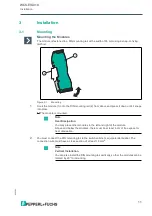

Installation
2
0
2
0
-0
3
13
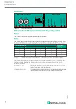
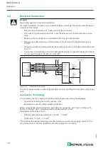
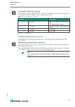
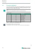
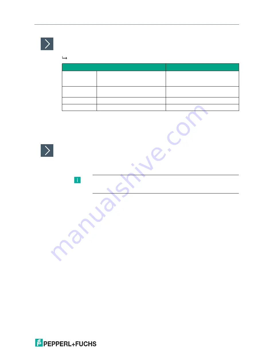
Connecting the Power Supply
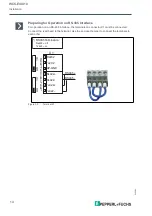
Connect the operating voltage (10 VDC ... 30 VDC) to terminals 1 and 2 of the 4-pin plug X2 on
the interface module. In addition, note the label on the module.
The "Power" LED lights up green.
Equipotential Bonding Connection
The connection to equipotential bonding occurs automatically when attaching to the DIN
mounting rail.
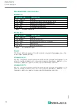
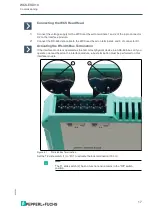
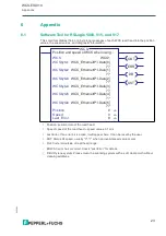
EtherNet/IP Communication Interface
This interface can be found on the interface module in the form of two 8-pin RJ45 sockets on
the bottom of the housing.
Insert the EtherNet/IP connector into one of the RJ45 socket(s) with the inscription "In" (cable
from master) or "Out" (further cable to the next EtherNet/IP slave).
Terminal
Description
1
UB+ (Pwr)
Operating voltage of interface mod-
ule/
operating voltage of sensor
2
0 V (Pwr)
Ground of interface module/ground of
sensor
3
not used
is not used
4
not used
is not used
Table 3.1
Terminal X2
Note
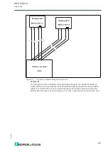
Ensure that the cable length to the neighboring EtherNet/IP participants is at
least 0.6 m.