


Commissioning
2
0
1
9
-0
7
23
Note!
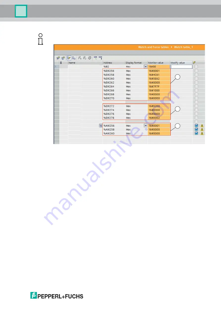
Output and Input Parameters in the Observation Table
Figure 4.9
Observation table
1. Result protocol
2. Teach result protocol
3. Output parameters
Information about input/output parameters can be found in the next chapter (see chapter 4.5).
1
2
3


