Pepperl+Fuchs VLX-F231-B6 Manual Download Page 17

VLX-F231-B6

Commissioning

 2

0

1

9

-0

7

17

6. If the rotary switch on the PROFIBUS side (PROFIBUS ID) is set to "7E" (= 126), the 

gateway uses a PROFIBUS address that is stored in the EEPROM. This address is 126 by 
default and can only be changed by a PROFIBUS master via the PROFIBUS itself. The 
address 126 is reserved for this purpose in the PROFIBUS, i.e., a slave with this address 
can never exchange data, but can only be configured with a new ID.

7. If the rotary switch is set to a value between 0 and 125, the gateway uses this PROFIBUS ID 

and it is not possible to change the setting via a master.

4.4

Integrating the Interface Module into the Network

Installing the GSD File

GSD file

 is required to operate the device. The GSD file can be downloaded from our 

website: www.pepperl-fuchs.com. Simply enter the product name or item number in the 
Product/Keyword field and click "Search." Select your product from the list of search results. 
Click on the information you require in the product information list, for example, Software. A list 
of all available downloads is displayed.

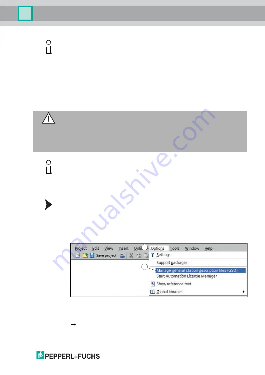
1. Start "TIA Portal V14."

Figure 4.1

GSD file

2. Under 

"Options"

 (1) in the menu bar, select the command 

"Manage general station 

description files (GSD)"

 (2).

 The 

"Manage general station description files"

 window opens.

Example!

The PROFIBUS ID is 26 decimal = 1A hexadecimal. The "PROFIBUS ID High" switch must be 
set to 1 and the "PROFIBUS ID Low" switch must be set to A. 

Warning!

Risk of injury due to incorrect configuration

An error during the configuration of the device can override the fail-safe function, causing a 
danger to people and machinery.

Ensure that the device is programmed exclusively by qualified personnel.

Only put devices into operation after they have been configured correctly.

Note!

Various configuration tools are available to allow you to configure the interface module. As an 
example, this manual describes the configuration of a Siemens control panel with the VLX-
F231-B6 interface module using the TIA Portal V14. If you are using a programmable logic 
controller (PLC) from a different manufacturer, the process will be similar to the one described 
here.

1

2

Summary of Contents for VLX-F231-B6

Page 1: ...R VLX F231 B6 VLX PROFIBUS DP Interface Module FACTORY AUTOMATION MANUAL...

Page 2: ...Terms of Delivery for Products and Services of the Electrical Indus try published by the Central Association of the Electrical Industry Zentralverband Elektrotechnik und Elektroindustrie ZVEI e V in i...

Page 3: ...plication 6 2 2 Dimensions 6 2 3 Design of the Device 7 3 Installation 10 3 1 Mounting 10 3 2 Electrical Connection 11 3 3 Dismounting 13 4 Commissioning 15 4 1 Introduction 15 4 2 Connecting the Sens...

Page 4: ...e EU type examination certificate EU declaration of conformity Attestation of conformity Certificates Control drawings Instruction manual Other documents 1 2 Target Group Personnel Responsibility for...

Page 5: ...in descending order as follows Informative Symbols Action This symbol indicates a paragraph with instructions You are prompted to perform an action or a sequence of actions Danger This symbol indicat...

Page 6: ...via the RS 485 interface and from the VLX F231 B6 interface module to the control panel via the PROFIBUS DP protocol You can connect up to four sensors If you connect several sensors they must have d...

Page 7: ...module overview 1 RS 485 terminator sliding switch behind the terminal block 2 X1 RS 485 interface 3 Mounting bracket 4 X2 Connection for power supply 5 PROFIBUS communication interface 6 Slide switc...

Page 8: ...error number or warning number and sends the number to the PROFIBUS master via the external diagnostic byte Error No Select ID Sensor address 8 4 2 1 0 0 0 1 0 0 0 1 0 1 0 1 0 0 2 1 0 0 0 3 Table 2 1...

Page 9: ...Error description LED8 LED4 LED2 LED1 0 0 0 0 0 Reserved 0 0 0 1 1 Hardware error 0 0 1 0 2 EEPROM error 0 0 1 1 3 Internal memory error 0 1 0 0 4 Fieldbus hardware error or incorrect fieldbus ID 0 1...

Page 10: ...to place The module is mounted 2 You must connect the DIN mounting rail to the switch cabinet s equipotential busbar The connection wire must have a cross section of at least 10 mm2 2 1 Note Heat Diss...

Page 11: ...crews with a 4 40 UNC thread To tighten the screws use a screwdriver with a blade width of 3 5 mm Observe the maximum tightening torque of 0 4 Nm Danger Device damage due to incorrect installation Inc...

Page 12: ...nator that is integrated in the interface module To do this slide the sliding switch to the on position or to the upper end position 4 If the module is not at the beginning or at the end you must slid...

Page 13: ...ion If the interface module is located at the beginning or end of the data cable to the control panel there must be a bus termination at this interface module To do this set the Termination PROFIBUS s...

Page 14: ...ule 1 Disconnect all the supply and signal lines Figure 3 3 Dismounting 2 Insert the screwdriver 2 into the groove of the mounting bracket 3 3 Press the screwdriver 2 in the specified direction until...

Page 15: ...using the interface labeled PROFIBUS 3 Connect the process device sensor For information on commissioning the process device sensor please refer to its manual 4 Ground the DIN mounting rail onto which...

Page 16: ...u therefore need a 9 pin D sub connector that you can plug into the 9 pin D sub socket on the device This plug is not included with the interface module 1 Connect the PROFIBUS connector to the D SUB s...

Page 17: ...e in the product information list for example Software A list of all available downloads is displayed 1 Start TIA Portal V14 Figure 4 1 GSD file 2 Under Options 1 in the menu bar select the command Ma...

Page 18: ...igure 4 3 Installing the GSD file 5 Select the GSD file to install by checking the box 1 to the left of the filename 6 Click the Install button 2 The installation process may take a few minutes Once t...

Page 19: ...this module into the network view 2 The device is displayed in the network view window 2 Figure 4 5 Connecting the PROFIBUS interfaces 4 Connect the device to the control panel To do this move the mou...

Page 20: ...signed an address range Creating Tag Tables A tag table must be created to be able to watch or control measured values In the tag table you can assign tags to input addresses or output addresses and a...

Page 21: ...by entering a value in the Address field 5 Note Information about the address range can be found in the next chapter see chapter 4 5 Note Address Range The address designations in this example are pro...

Page 22: ...n Watch and force tables and double click on Add new watch table 4 2 Click the field in the Address column A list of addresses that you have defined in the tag table is displayed 3 From the list selec...

Page 23: ...Output and Input Parameters in the Observation Table Figure 4 9 Observation table 1 Result protocol 2 Teach result protocol 3 Output parameters Information about input output parameters can be found...

Page 24: ...tion table To do so proceed as follows 1 Enter an output parameter AW256 from 0 to 1 in the observation window Right click in the Modify value selection field 1 to do this 2 In the context menu select...

Page 25: ...In order to run the Teach process again Bit 0 must be reset Input Parameters Byte Bit 7 Bit 6 Bit 5 Bit 4 Bit 3 Bit 2 Bit 1 Bit 0 Byte 0 Reserved 0 0 0 0 0 0 0 0 Byte 1 Trigger 0 0 0 0 0 0 0 1 Byte 2...

Page 26: ...05 PosZ04 PosZ03 PosZ02 PosZ01 PosZ00 Byte 11 Checksum 0 xor xor xor xor xor xor xor Byte 12 0 0 0 0 0 0 0 0 Byte 13 0 0 0 0 0 0 0 0 Byte 14 0 0 0 0 0 0 0 0 Byte 15 0 0 0 0 0 0 0 0 Byte 16 0 0 0 0 0 0...

Page 27: ...A6 QA5 QA4 QA3 QA2 QA1 QA0 Byte 21 Quality B 0 QB6 QB5 QB4 QB3 QB2 QB1 QB0 Byte 22 Quality C 0 QC6 QC5 QC4 QC3 QC2 QC1 QC0 Byte 23 Quality D 0 QD6 QD5 QD4 QD3 QD2 QD1 QD0 Byte 24 Checksum 0 xor xor xo...

Page 28: ...Group 68307 Mannheim Germany Tel 49 621 776 0 E mail info de pepperl fuchs com USA Headquarters Pepperl Fuchs Inc Twinsburg Ohio 44087 USA Tel 1 330 4253555 E mail sales us pepperl fuchs com Asia Pac...

Reviews: