


Configuration and Analysis with DTM via IO-Link
2
0
2
0
-1
1
41
Scaling the X-Axis and Navigating to Significant Data
Use the left mouse button and Shift key to zoom the display area in the x direction; doing so
zooms in on selected data.
While holding down the Shift key, move the mouse cursor into the display area until the mouse
cursor changes to a magnifying glass icon (+). Hold down the left mouse button and define the
required magnification area with the selection window. You can repeat this process multiple
times.
The x-axis is then displayed in the corresponding zoom ratio. A scroll bar appears for the x-
axis and y-axis, allowing you to scroll through the adjacent areas.
You can undo the zoom by holding down the Alt key and clicking the left mouse button in the
display area.
To zoom in / out:
•
Zoom in >> press left mouse button and Shift key
•
Zoom out >> press left mouse button and Alt key
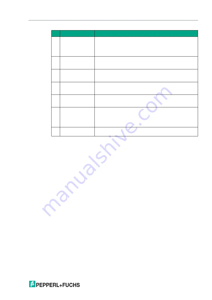
6
Output
By clicking on the check box, you can enable or disable display of
the output status (0/1) in the display area in the form of a green
line.
The analog output value is displayed in the diagram for an analog
output.
7
Interval
You can use the "Interval" selection function to specify the time
interval at which data is recorded in the graphic. There are several
fixed intervals available between 100 ms and 1 hour.
8
Start logging
Only for event-driven data logging
You can use the "Start recording" button to start and end event-
driven recording of data in a file (data logging).
9
Settings for data log-
ging
Only for event-driven data logging
You can use the "Settings for data logging" button to specify
events for data recording and the name of the log file via a menu.
10
Display area
In the display area, the "Distance" and "Output" check boxes can
be used to display selected measured variables and output sta-
tuses in the form of line diagrams.
11
Output logic (green
line)
The green line indicates the logical status of the output (right y-
axis) for the switch point set in the
Output configuration
menu
option.
The analog output value is displayed (likewise right y-axis) for a
sensor with analog output.
12
Distance value line
(blue line)
The blue line shows the distance value measured from the sensor
(left y-axis).
Table 7.3
No. Name
Description


