


Safety Manual SIL KFD0-RSH-1(-Y2), KFD2-SL-4
Planning
2
014-07
9
2.4
Characteristic Safety Values
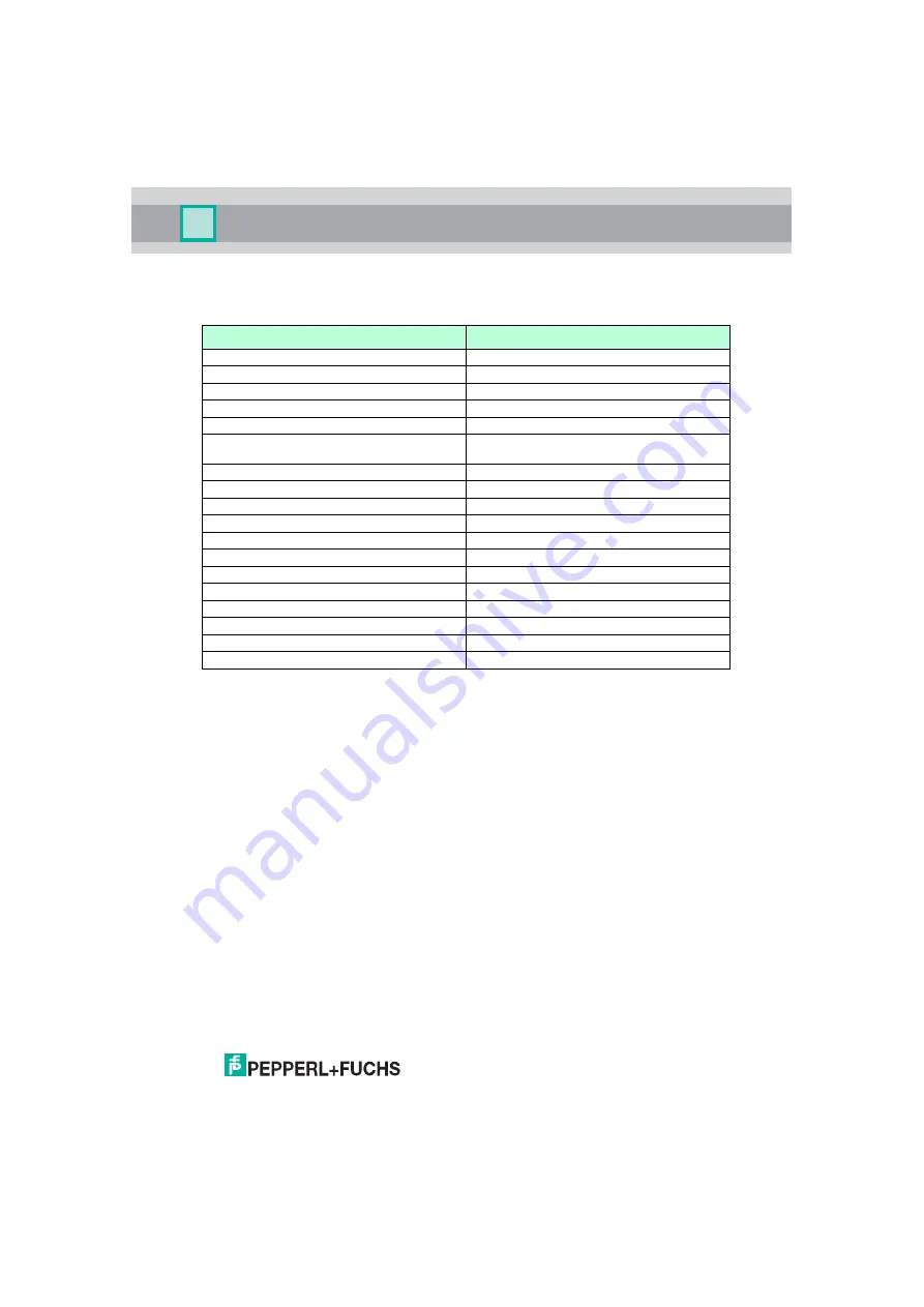
KFD0-RSH-1
Parameters acc. to IEC 61508
Values
Assessment type and documentation
FMEDA report
Device type
A
Mode of operation
Low Demand Mode or High Demand Mode
HFT
0
SIL
3
Safety function
Output relay in OFF state when input is de-
energized
s
251.6 FIT
dd
0 FIT
du
0.4 FIT
no effect
69.6 FIT
total (safety function)
252 FIT
SFF
99.8 %
MTBF
1
452 years
PFH
4.00 x 10
-10
1/h
PFD
avg
for T
proof
= 1 year
1.75 x 10
-6
PFD
avg
for T
proof
= 2 years
3.50 x 10
-6
PFD
avg
for T
proof
= 5 years
8.76 x 10
-6
Reaction time
2
< 20 ms
1
acc. to SN29500. This value includes failures which are not part of the safety function.
2
Time between fault detection and fault reaction.
Table 2.1


