


SLCT* and SLCT*/35 safety light curtains
Product Description
2
7
1
6
9
5
2
0
1
7
-1
2
11
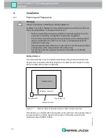
3.2
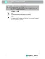
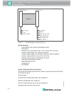
Indicators and Operating Controls
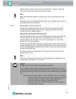
The transmitter has two LEDs to display its operating status.
The receiver has five LEDs to display its operating status.
Figure 3.2
Displays on the transmitter and receiver units
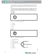
3.3
Interfaces and Connections
The electrical connections of the safety light curtain are made using M12 plug-in
connectors. The transmitter has a 4-pin connector and the receiver an 8-pin plug-
in connector.
Connect the power supply and, depending on the application, the test signal to
the transmitter unit. The mode can also be selected via the A/B mode input.
No.
Designation
LED Color
Meaning
1
Power LED
Green
Transmitter and receiver units operating
2
A/B mode,
status
Yellow
Indicator flashing at 1 Hz: testing time
exceeded
or A/B mode input level change
Indicator flashing at 5 Hz: internal fault
3
OSSD OFF
Red
OSSDs switched off
4
OSSD ON
Green
OSSDs switched on
5
Restart/status
Yellow
On: protection field free: system ready to
start
Indicator flashing at 1 Hz: external fault
Indicator flashing at 2.5 Hz: insufficient
functional reserve
Indicator flashing at 5 Hz: internal fault
6
Mode A/B
Yellow
Off: mode A
On: mode B
1 Power
green
2 Mode A/B, Status yellow
3 OSSD OFF
red
4 OSSD ON
green
5 Restart/Status
yellow
6 Mode A/B
yellow
Transmitter
Receiver
1
2
3
5
4
6
1


