


IDM-Z1-161-M-1D-J1-BT-N-N0, IDM-Z1-161-M-1D-J1-BT-P-N0, IDM-Z1-261-M-2D-
J1-BT-N-N0
0
0
0
0
-0
0
25
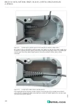
Direct connection of the base station without plug/coupling to the
supply module with USB interface
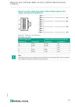
Figure 4.16
RJ50 plug - connection layout
Base station cordset
Cordset assignment
Supply module terminal compartment
RJ45 pinout
Strand color
Designation
Assignment
2
Green
D+2SL
X9
10
White
D-2SL
X10
X11
4
Black
GND
X12
7
Brown
+UB
X13
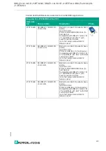
Note
Information relating to programming from the SICK AG manual (www.SICK.com) is required for
the complete commissioning of the handheld scanner.