


0
0
0
0
-0
0
20
IDM-Z1-161-M-1D-J1-BT-N-N0, IDM-Z1-161-M-1D-J1-BT-P-N0, IDM-Z1-261-M-2D-
J1-BT-N-N0
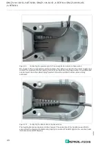
Figure 4.9
Connecting the power supply for the non-explosion-hazardous base station
To connect in the non-explosion-protected area, the cable to connect to the power supply and
to the PC is inserted into the opening for this at the bottom of the base station. An audible click
can be heard when the cable is fully inserted. It must be verified that the cable is firmly
anchored.
Figure 4.10
Connecting the RJ50 cable to the base station
The handheld scanner is placed in the charger. The underside of the handle is used first to
ensure that the charging contacts are properly connected. The LED light on the scanner head
indicates successful charging.