


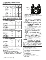


To Regenerant
Tank
BRINE REFILL
Cycle 7
FAST RINSE
Cycle 4
BACKWASH
Cycle 5
FAST RINSE
Cycle 6
SERVICE
BACKWASH
Cycle 1
REPRESSURIZE
Cycle 3
From Regenerant
Tank
BRINE/SLOW RINSE
Cycle 2
Figure 1 Flow Patterns
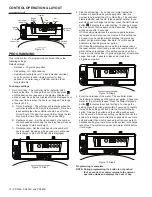
Location Selection
Location of a water treatment system is important . The
following conditions are required:
•
Level platform or floor.
• Ambient temperatures over 34°F (1°C) and below 120°F
(49°C) .
• Water pressure below 125 psi (8 .61 bar) and above
20 psi (1 .4 bar) .
• In Canada the water pressure must be below 100 psi
(6 .89 bar) .
• Constant electrical supply to operate the controller .
• Total minimum pipe run to water heater of ten feet (three
meters) to prevent backup of hot water into system .
• Local drain or tub for discharge as close as possible .
• Water line connections with shutoff or bypass valves .
• Must meet any local and state codes for site of
installation .
• Valve is designed for minor plumbing misalignments . Do
not support weight of system on the plumbing .
• Be sure all soldered pipes are fully cooled before
attaching plastic valve to the plumbing .
• Room to access equipment for maintenance and adding
salt to tank .
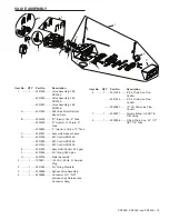
A
15.00in
381mm
36.91in
937.55mm
B
8.75in
222.25mm
4.00in
101.60mm
52.33in
1329.11mm
25.36in
644.23mm
15.00in
381mm
36.91in
937.55mm
50.51in
1283.07mm
8.75in
222.25mm
4.00in
101.60mm
C
PRF26K
PRF34K
PRF40K
A
48 .3 in (1266 .8 mm) 52 .33 in (1329 .2 mm) 48 .4 in (1229 .4 mm)
B
46 .5 in (1181 .1 mm) 50 .51 in (1282 .9 mm) 46 .6 in (1183 .6 mm)
C
24 .36 in (618 .7 mm) 25 .36 in (644 .23 mm) 26 .36 in (669 .54 mm)
System Specifications
Model
PRF26K
PRF34K
PRF40K
Recharge Style
Meter - Demand Meter - Demand Meter - Demand
Media Tank Size
8" x 44"
9" x 48"
10" x 44"
Resin Volume
0 .80 Ft
3
1 .04 Ft
3
1 .25 Ft
3
Recharge (Salt)
Tank Size
14" x 34"
14" x 34"
14" x 34"
Salt Storage
240 lbs
240 lbs
240 lbs
Drain Water Rate
2 .1 GPM
2 .1 GPM
2 .7 GPM
Service
Connection Size
1" NPT
1" NPT
1" NPT
Drain Connection
Size
1/2" NPT
1/2" NPT
1/2" NPT
Recharge (Brine)
Connection Size
3/8" NPT
3/8" NPT
3/8" NPT
Installation
Space
Requirements
25" W x 15" D
25" W x 15" D
26" W x 15" D
Shipping Weight
78 lbs
95 lbs
110 lbs
EQUIPMENT INSTALLATION
continued
4 • PRF26K, PRF34K, and PRF40K


