


23833A245
8
5. Lay pump on its side. Place a flat screwdriver
in the slot in the bottom of the shaft and turn the
impeller counterclockwise to remove it from the
shaft. A blow from a rubber hammer may be
necessary to loosen the impeller. Discard old seal
part.
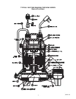
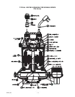
6. Remove the four flat head screws holding the
upper half of volute to housing. Note position of
discharge in relation to switch clamp.
7. To assemble the new ceramic seal seat into your
new stator housing assembly, clean the seat cavity
thoroughly and follow Steps 7 & 8 “For Shaft Seal
Only Replacement”. NEVER USE OLD SEAL
PARTS. USE ONLY COMPLETELY NEW SEALS.
8. Assemble the upper half of the volute to housing
with the four flat head screws. Position discharge
the same as before in relation to switch clamp.
9. Make sure the shaft surface is clean and lightly
oiled. Press by hand the rotating half of the shaft
seal onto the shaft. Be sure the rotating carbon
washer is positioned adjacent to the ceramic seat.
10. Screw the impeller clockwise onto the shaft using
a screwdriver to hold the shaft from turning and
tighten impeller. Use Loctite or equal on shaft
threads.
11. Place pump upright on top of lower volute half. Be
sure mating parts are together and reassemble the
eleven machine screws and tighten.
12. Check that the impeller turns freely.
13. Guide the four motor wires up through a common
hole in the bearing plate and place the protective
plastic tube over the four motor wires.
14. Position the o-ring into cap and reconnect the four
motor wires as shown in wiring diagram. The two
green ground wires connect to the pins nearest the
‘G’ marked on the cap.
15. Put oil in the motor housing using only Myers
submersible transformer oil. The oil should be
about 1/2” above the surface of the bearing plate.
16. Reinstall the top thermoplastic cap, making sure
the o-ring is in position on the cap. Tighten the top
six screws snug, but do not overtighten.
17. Be sure the 1/8” NPT pipe plug is in the top cap.
18. Plug pump into receptacle to test operation. Pump
must run quiet and free of vibration.
NOTE: When replacing top cap with a new one, be
sure the jumper wire and pipe plug are in place. See
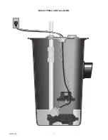
wiring diagram. Tether level control to motor housing
with float extended 3-5/8” to 4”.
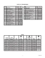
WIRING DIAGRAM
MOTOR REISTANCE CHART
Winding
Locked
Resistance
Max.
Rotor
Model
HP Speed
V
Ph
in Ohms
Amps Amps
ME40
4/10
1550 115 1
1.2
12.0
16.0
ME40
4/10
1550 230 1
4.3
6.0
8.2
ME40AG 4/10
1650 115 1
2.0
8.0
17.6
ME40AG 4/10
1650 230 1
9.1
4.0
8.8


