

INTELLICONNECT
™
CONTROL AND MONITORING SYSTEM
CONTROL BOARD REPLACEMENT KIT
THIS GUIDE PROVIDES IMPORTANT INFORMATION ON REMOVING AND REPLACING YOUR INTELLICONNECT™
CONTROL AND MONITORING SYSTEM’S CONTROL BOARD. FOLLOW THE INSTRUCTIONS BELOW TO ENSURE
CORRECT INSTALLATION OF THE NEW BOARD.
Uninstalling the Old Control Board
1. Ensure power is turned off at the circuit breaker.
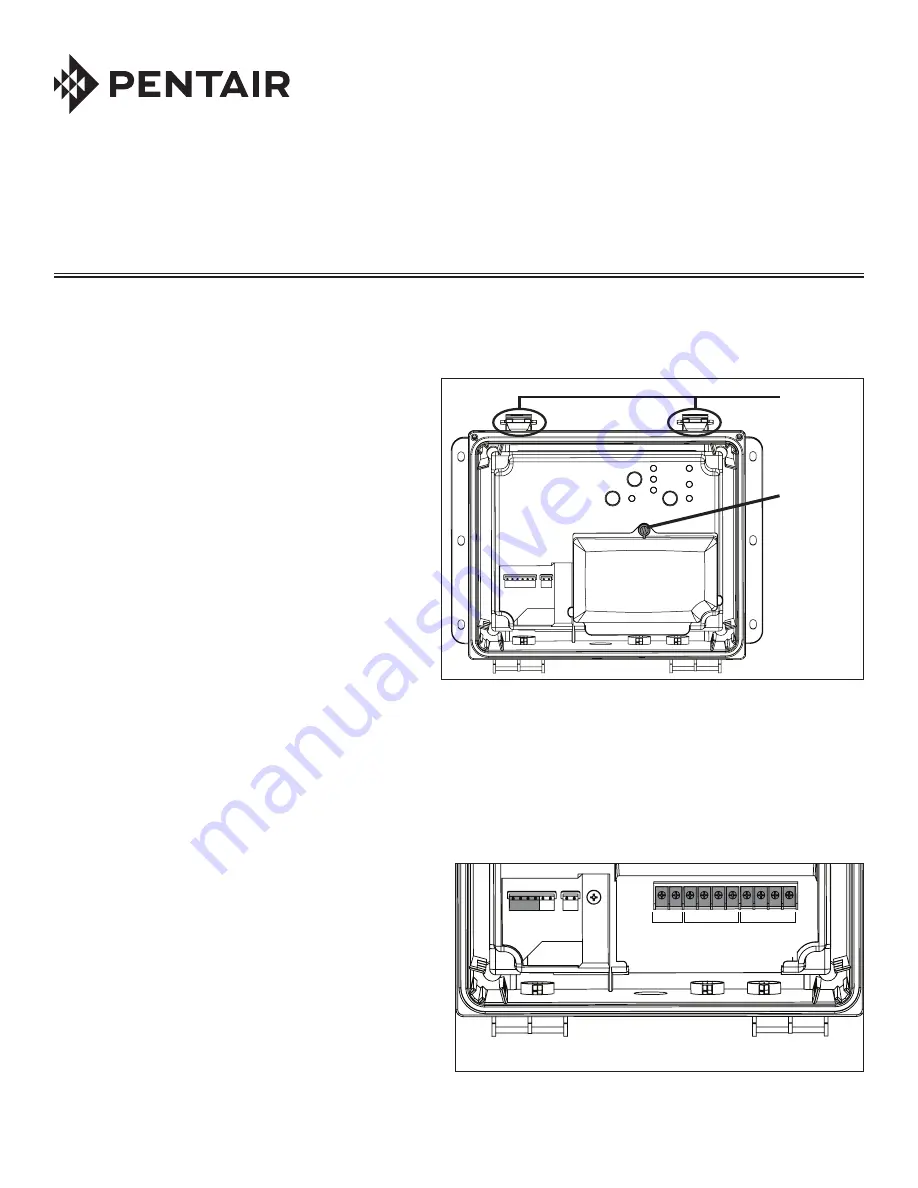
2. Open the enclosure by unfastening the two retaining
clips at the top of the enclosure (see
Figure 1
).
3. Uninstall the retaining screw securing the wiring
compartment cover (see
Figure 1
) and remove the
wiring compartment cover.
4. Take note of the terminals that each wire is wired
to. Uninstall and remove all AC power, relay and
RS-485 wiring from the enclosure (see
Figure 2
).
5. Remove the four (4) Phillips-head screws from the
corners of the control board assembly.
Note:
Save these retaining screws for later use.
Replacement screws are NOT provided in this kit.
6. Remove the control board assembly from the
enclosure.
Installing the New Control Board
1. Seat the new control board assembly inside the enclosure.
Note:
Handle the control board with care. Static discharge or handling the board with dirty or wet hands may damage the
control board.
2. Using the four (4) retaining screws that were removed when uninstalling the old control board, secure each corner of the
new control board.
3. Uninstall the retaining screw securing the high voltage wiring compartment cover (see
Figure 1
) and remove the high
voltage cover.
4. Reinstall all necessary AC power, relay and RS-485
wiring to the appropriate terminals (see
Figure 2
).
5. Reinstall the high voltage compartment cover.
6. Return power to the IntelliConnect at the circuit breaker.
7. Remove power from the IntelliConnect for ten (10)
seconds and then reconnect.
8. Open your computer, smartphone or tablet’s wireless
settings.
9. You should see an available access point titled
“IntelliConnectPIFxxxxxxx”. Select this access point
to connect to IntelliConnect.
10. Open your smartphone, tablet or computer’s web browser.
11. Type
192.168.123.1
into the address bar and press enter. This will take you to the pairing page.
RS-485
Terminal
Relay 2
Relay 1
AC
Power
Figure 2
Figure 1
Wiring
Compartment
Retaining
Screw
Retaining
Clips


