4
Hydraulic System Operation
Pump Repair Instructions
Plunger Replacement.
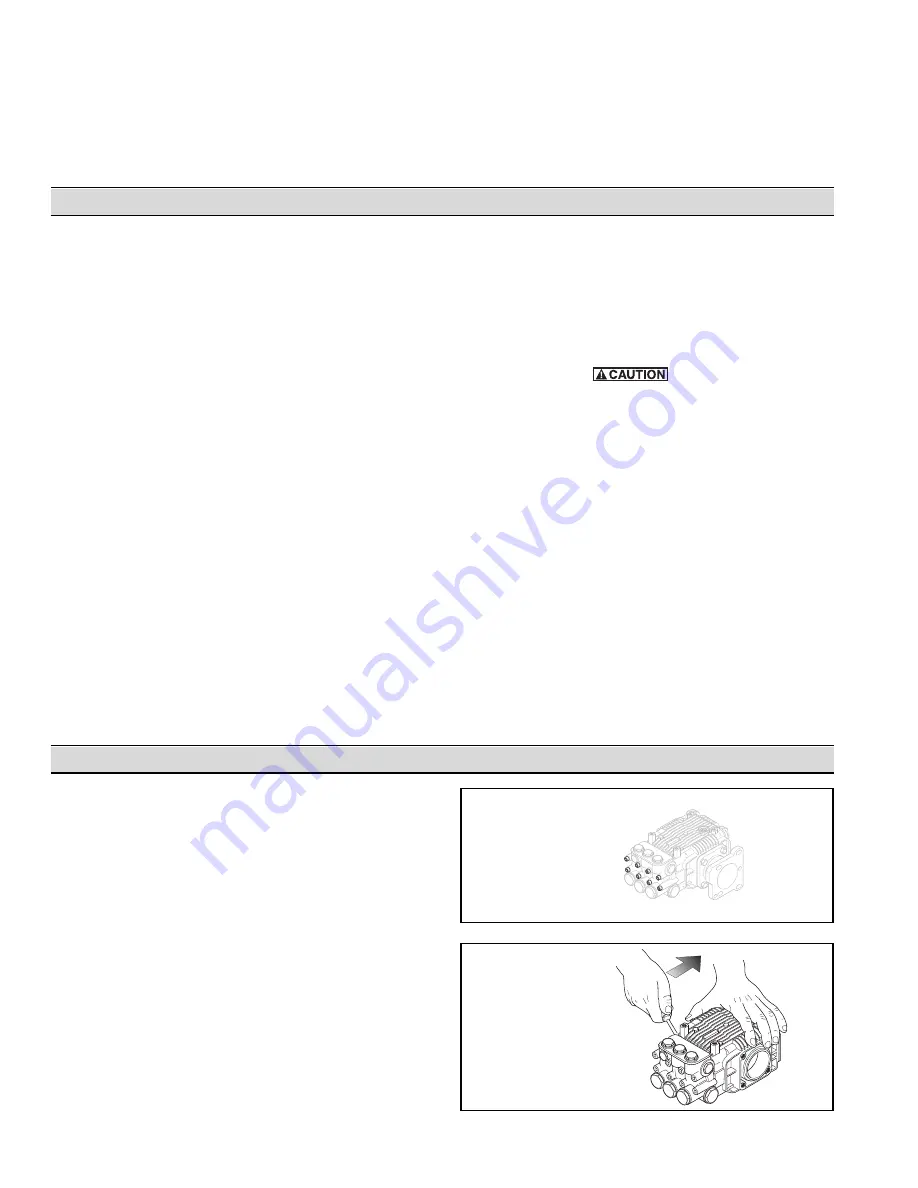
1. Using a metric allen wrench, remove the Socket
Head Cap Screws securing the Pump Head to the
Pump Body (See Figure 3).
2. While turning the Crankshaft, use two screwdrivers to
carefully pry between the Pump Head and Pump
Body to remove the Pump Head (See Figure 4).
3. Remove the plunger Retaining Nut and the Plunger
Retaining Nut Washer (See Figures 5).
4. Slide the Plungers off the Piston Guides (See
Figure 5).
5. Remove and discard the O-rings (See Figure 5).
6. Remove the Slinger Ring (See Figure 5).
Figure 3
Remove
Socket Head Cap
Screws
Figure 4
While turning the
crankshaft, use
screwdrivers to pry
the pump head off.
Hydraulic Systems
There are three types of Hydraulic Systems: Open center,
Closed Center (Pressure Compensated), and Closed
Center Load Sensing (Flow and Pressure Compensated).
Open Center Systems
In an Open Center System, the hydraulic pump puts out a
constant flow. If the Pump puts out more than the Motor
can use, a portion of the oil must be bypassed around the
Motor. The Bleeder Bypass Screw allows the fluid to
bypass around the Motor. When the oil is bypassed
around a loop and does no work, the energy put into it by
the Pump turns into heat. Therefore, this should only be
used on smaller Open Center Systems where the amount
of oil that must be bypassed is minimal.
Closed Center (Pressure Compensated) Systems
Closed Center (Pressure Compensated) Systems have a
Variable Displacement Pump that will deliver flow at the
necessary rate to maintain a specified pressure. The Flow
Control Valve should be installed at the Motor Inlet to
control the flow according to the Model requirements.
Closed Center Load Sensing Systems (Flow and
Pressure Compensating)
The Closed Center Flow Compensated System is a
variation of the Pressure Compensated System, designed
primarily for more efficient operation and the generation of
less heat. It works on the principle of maintaining a
constant pressure drop from the pump to the working port
of the Selector Valve. Any variation in demand at the
Motor will cause a change in flow. The system senses this
change in flow due to the change in pressure drop across
the Valve and causes the pump to compensate by varying
the Pump flow
Do not bypass oil. Use a Flow Control at the Motor
Inlet to control the flow and speed of the motor.
Hydraulic Oil
The specifications for the Hydraulic-Driven Pressure
Washer where compiled using Mobil DTE-26 hydraulic oil
at a temperature of 140° F [60° C]. Using other type of oil
and different temperatures will result in different flow
requirements to replicate these Pressure Washer
performance specifications. These specifications are a
guide for initial start-up.
Keep all hydraulic connections clean. The recommended
filter for the hydraulic motor is one that removes
particulates greater than and including 10 microns. The
>10 micron filter should be placed on the return line of the
hydraulic system to mitigate the risk of contaminating the
oil tank.
Change the oil after 40 hours of break-in operation.
Thereafter, change the oil every year or 500 hours,
whichever comes first.
Care of the Pump
After each use, flush the pump with a neutralizing solution
for the liquid pumped. Follow this with a clear water rinse.
For storage under freezing conditions, flush the pump with
a 50/50 solution of automotive-type antifreeze and water.
Bypass Operation
During Bypass Operation (when water is diverted back to
the pump inlet side) a temperature rise occurs. A Thermal
Relief Valve is provided to maintain the maximum water
temperature at 145° F [63° C].
Summary of Contents for HYPRO 1802C
Page 11: ...11 Mounting Dimensions Figure 17 Mounting Dimensions ...
Page 18: ...18 Notes ...
Page 19: ...19 Notes ...


