


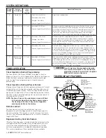


SYSTEM DEFINITIONS
System
Number
System
Description
# of
Tanks/
Controls
Type
Operation Discussion
4
Single Unit
1
Time Clock: No Meter
Immediate: One Meter
Delayed: One Meter
Remote Signal Start: No Meter
Single tank configuration.
5
Interlocked
2, 3, or 4
Immediate: All Meters
Remote Signal Start: No Meter
All tanks in parallel supplying treated water. Each unit in the system
will have its own flow meter/sensor input. The control will delay the
start of Regeneration if another unit is already in Regeneration. Once
that unit has completed a Regeneration cycle, and has returned to
Service,the unit with longest regeneration queue time will begin
Regeneration. No more than one unit will be in Regeneration at a time.
6
Series
Regeneration
2, 3, or 4
Immediate: One Meter
Delayed: One Meter
Remote Signal Start: No Meter
All tanks in parallel supplying treated water. Only #1 control will
monitor flow meter/sensor input. When a regeneration is required
for the system, it will regenerate valve address #1 first, immediately
followed by #2, then #3, then #4 if installed. No more than one unit
will be in Regeneration at a time.
7
Twin
Alternating
2
Immediate: One Meter
Remote Signal Start: No Meter
One tank online supplying treated water, one tank in Standby. Only
#1 control will monitor its flow meter/sensor input. Regeneration of
a unit will begin after the other control has left Standby and returned
to Service. When the Regeneration cycle is complete, the regenerated
unit will enter Standby. Standby on each tank is controlled by the 24
VAC solenoid bypass on the NXT circuit board.
9
Multiple Tank
Alternating
2, 3, or 4
Immediate: All Meters
Remote Signal Start: No Meter
One, two, or three tanks online supplying treated water, one tank in
Standby. Meter/sensor input is required on each tank. Regeneration of
a unit will begin after the other control has left Standby and returned
to Service. When the Regeneration cycle is complete, the regenerated
unit will enter Standby. Standby on each tank is controlled by the 24
VAC solenoid bypass on the NXT circuit board.
TIMER OPERATION
Timer Operation During Programming
The timer enters the Program Mode in Standby or Service
Mode as long as it is not in regeneration. While in the Program
Mode the timer continues to operate normally monitoring
water usage. Timer programming is stored in memory
permanently.
Timer Operation During A Power Failure
All program settings are stored in permanent memory. Current
valve position, cycle step time elapsed, and time of day are all
stored during a power failure. These settings will be restored
upon power re-application. Time is kept during a power failure,
and time of day is adjusted upon power up (as long as power is
restored within 12 hours).
NOTE: The time of day on the main display screen will flash
for 5 minutes when there has been a power outage.
The flashing of the time of day can be stopped by
pressing any button on the display.
Remote Lockout
The timer does not allow the unit/system to go into
Regeneration until the Regeneration Lockout Input signal to
the unit is cleared. This requires a contact closure to activate
the unit. The recommended gauge wire is 20 with a maximum
length of 500 feet.
Regeneration Day Override Feature
If the Day Override option is turned on and the valve reaches the
set Regeneration Day Override value, the Regeneration Cycle
starts if no other networked unit is in Regeneration. If other
units are in regeneration, it is added to a regeneration queue.
This occurs regardless of the remaining volume available.
WARNING:
Transformer must be grounded and ground
wire must be terminated to the circuit board
grounding screw before installation. Supplied
40VA transformer must be used.
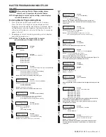
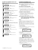
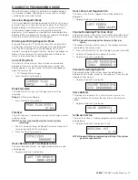
TIMER DISPLAY FEATURES
Shift Button
Adjusts Values to the Left
Up Button
Adjusts Values Up
Volume Remaining
Status LED
Diagnostic Button
View Flow Rate, Peak Flow
Rate, Totalizer, Hours
Between Last Two
Regenerations, Hours Since
Last Regeneration, Adjustable
Volume Remaining, Valve
Position, Send & Receive
Errors, Software Version
Extra Cycle Button
Cycle Valve in
Regeneration/Cycle
Programming Steps
System
Number
Valve
Address
Valve State
(INI, RGQ, SRV, LCK)
Flow
Indicator
Time
of Day
Display Screen
Time of Day alternates
with Error Screen
Example: Valve #, Volume
Remaining, Errors
Down Button
Adjusts Values Down
Figure 5
6 •
FLECK
7000 NXT Service Manual


