

2 / 2
THERMAL MANAGEMENT SOLUTIONS
EN-DigiTraceE507SLS-IM-H56913 01/13
WWW.THERMAL.PENTAIR.COM
© 2001-2013 Pentair.
PN 137863
NORTH AMERICA
Tel: +1.800.545.6258
Fax: +1.800.527.5703
Tel: +1.650.216.1526
Fax: +1.650.474.7711
[email protected]
EUROPE, MIDDLE EAST, AFRICA
Tel: +32.16.213.511
Fax: +32.16.213.603
[email protected]
ASIA PACIFIC
Tel: +86.21.2412.1688
Fax: +86.21.5426.2917
[email protected]
LATIN AMERICA
Tel: +55.11.2588.1400
Fax: +55.11.2588.1410
[email protected]
Pentair and DigiTrace are owned by Pentair or its global affiliates. All other trademarks are the property of their respective owners. Pentair reserves the
right to change specifications without prior notice.
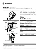
Figure 4. Contactor control
Figure 1. Pipe-sensing
C
NO
NC
For switching heat-tracing loads greater than 22 A
or switching multiple heat-tracing circuits.
Ø
G
G
N
Ø
Ø
Heating
Cable
Power
connection
Thermostat bulb
(see "Positioning"
instructions above
for mounting details)
Braid
Control
thermostat
Control
thermostat
GFEPD
C
C
NO
NC
NO
NC
Thermostat bulb
(see "Positioning"
instructions above
for mounting details)
or
208-V or 240-V supply – 240-V heater
120-V supply – 120-V heater
277-V supply – 240-V heater
Ø
C
G
C
N
A
N
B
N
C
Ø
B
Ø
A
120-V or
277-V
coil
Braid
120- V supply – 120-V heater or
277-V supply – 240-V heater
GFEPD
Figure 2. Low-temperature alarm
C
NO
NC
Ø
G
N
Ø
Ø
Alarm
Thermostat bulb
(see "Positioning"
instructions above
for mounting details)
Control
thermostat
GFEPD
or
208-V or 240-V supply
120-V supply – 120-V heater
277-V supply – 240-V heater
Figure 3. High-temperature alarm
C
NO
NC
Ø
G
N
Ø
Ø
Alarm
Thermostat bulb
(see "Positioning"
instructions above
for mounting details)
Control
thermostat
GFEPD
or
208-V or 240-V supply
120-V supply – 120-V heater
277-V supply – 240-V heater
Heating
cable C
Heating
cable B
Heating
cable A
WIRING
INSTALLING THE THERMOSTAT
1. Verify that the thermostat is
suitable for the area where it is to
be installed.
2. Check the line voltage and the
heat-tracing load to ensure that
the thermostat ratings are not
exceeded.
3. Mount the unit using unistrut or the Raychem universal
mounting bracket (UMB-263757) in a position that prevents
condensation from draining into the enclosure from the
connecting conduit (see diagram above).
POSITIONING THE SENSOR BULB
4. Position the bulb in the
lower quadrant of the pipe
as shown in the diagrams
to the left. Place the bulb
at least three feet from
pipe supports, valves, or
other heat sinks; protect
the capillary from kinks or
bends less than 1⁄2 inch in
radius.
5. Tape the bulb firmly to the pipe with AT-180 aluminum tape,
making sure there is no air space between the bulb and pipe.
Do not overlap the bulb and heating cable with the same piece
of AT-180 tape.
6. For metal-tank-wall sensing, use the BCK-35 bulb clamp
(purchased separately) and install the clamp per the
instructions provided. Make sure there is no air space between
the tank wall and the bulb.
For installation on plastic tanks, contact Pentair Thermal
Management at (800) 545-6258.
SETTING THE THERMOSTAT
7. Set the thermostat dial to the desired temperature, then finish
wiring.
8. Complete insulating. Do not turn the system on until the bulb is
covered with thermal insulation.
9. Fill the piping or tank. Once the thermostat has begun to cycle,
check the fluid temperature with an immersed thermostat
(best for plastic systems) or an accurate temperature indicator.
Adjust the dial setting if necessary.
Conduit
drain
90
Heating cable
Control thermostat bulb
AT-180 tape
AT-180 tape
Heating cable
Control thermostat bulb
Double traced
Single traced