

1 / 2
E507S-LS
LINE-SENSING THERMOSTAT FOR HAZARDOUS LOCATIONS INSTALLATION INSTRUCTIONS
THERMAL MANAGEMENT SOLUTIONS
EN-DigiTraceE507SLS-IM-H56913 01/13
DESCRIPTION
The E507S-LS thermostat is designed for controlling heat-tracing
systems in hazardous locations. The E507S-LS can be used to
control heat-tracing circuits in a pipe-sensing mode (see Figure 1
on back page), to indicate low-temperature (see Figure 2) or high-
temperature (see Figure 3) alarm conditions, or to control the coil
on a contactor (see Figure 4).
APPROVALS
SPECIFICATIONS
Enclosure
NEMA 4, 7, 9, lacquer-coated cast-aluminum
housing, stainless-steel hardware
Entries
One 3/4 in. NPT conduit hub
Set point range
25°F to 325°F (–4°C to 163°C)
Sensor exposure
limits
–40°F to 420°F (–40°C to 215°C)
Housing exposure
limits
–40°F to 140°F (–40°C to 60°C)
Switch
SPDT
Electrical rating
22 A at 125/250/480 Vac
Accuracy
±6°F (±3.3°C)
Deadband
2°F to 12°F (1.1°C to 6.7°C) above actuation
temperature
Set point
repeatability
±3°F (±1.7°C)
Sensor type
Fluid-filled (silicone) bulb and 9 ft (2.7 m)
capillary
Sensor material
300 series stainless steel
Connection
terminals
Screw terminals, 10–14 AWG (2–5 mm
2
)
Class I, Div. 1 and 2, Groups B, C, D
Class II, Div. 1 and 2, Groups E, F, G
Class III
Hazardous locations
This component is an electrical device. It must be installed
correctly to ensure proper operation and to prevent shock or
fire. Read these important warnings and carefully follow all the
installation instructions.
Component approvals and performance are based on the use of
specified parts only. Do not use substitute parts or vinyl electrical
tape to make connections.
WARNING:
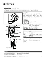
4.0 in. (102 mm)
4.5 in. (114 mm)
Ø.28 in. (7 mm)
mounting hole
(4X)
4.5 in.
(114 mm)
6.6 in.
(168 mm)
4.0 in.
(102 mm)
8.0 in.
(202 mm)
Adjusting knob
Removable knob cover
4.0 in. (102 mm)
1.2 in. (30 mm)
2.0 in.
(50 mm)
3⁄4 in. NPT conduit entry
0.3 in. (9 mm)
Terminal
block