


32
Installation
→
Mount the control head on the hub flange (seamlessly 360° rotatable).
→
Secure control head with the two locking screws (shoulder screws M5) in the middle groove of the hub flange
to prevent it from being pulled off the hub flange – tightening torque: max. 3.2 Nm (see "Fig. 11: Schematic
diagram of the control head - process valve adaptation").
7.2.3.
Realignment of the control head
If necessary, the control head can be realigned, in particular if properly accessible installation of the pneumatic supply
lines is not possible due to spatial conditions. This might also be required for operational aspects (accessibility of
the manual control) and because of electrical connection possibilities.
Procedure:
→
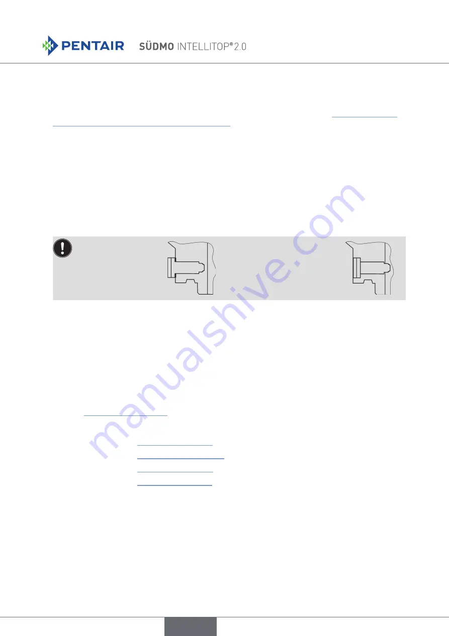
Loosen the locking screws (shoulder screws M5) slightly until the underside of the screw head is flush with
the auxiliary surface of the housing.
The locking screw has
been loosened sufficiently
when the lower side of
the screw head is flush
with the auxiliary surface
of the housing.
The locking screw is sufficiently
tightened when the upper side of
the screw head is flush with the
auxiliary surface of the housing.
Tightening torque: max. 3.2 Nm
→
Rotate the control head until the desired alignment has been achieved.
→
Secure the control head with locking screws again until the upper side of the screw head is flush with the
auxiliary surface of the housing. The locking screws have
no
sealing function.
The control head is
not fixed
in place
by the locking screws but is merely secured against being pulled off the hub flange.
7.2.4.
Assembly of the pneumatic and electrical connections
Pneumatic installation
see Chapter "9. Pneumatic Installation"
Electrical installation
24 V DC:
see Chapter "10. 24 V DC - Design"
AS-Interface:
see Chapter "11. AS Interface - Design"
DeviceNet:
see Chapter "12. DeviceNet Design"
120 V AC:
see Chapter "13. 120 V AC Design"
7.2.5.
Recommended auxiliary materials
Silicone grease Paraliq GTE 703 for easy lubrication of the EPDM seals.
english