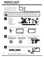
background image

Rev. A  2-4-2000

P/N 471438

INDOOR INSTALLATION

The installation of flueing systems should conform with
the latest edition of BS 5440:1.

All products of combustion and flue gases must be
completely removed to the outside atmosphere through
a flue pipe which is connected to the draft divertor. A
flue pipe extension of the same size must be
connected to the draft divertor and extended at least
600 mm higher than the highest point of the roof within
a 3 m horizontal radius, and at least 1 m higher than
the point at which it passes through the roof; see
Figure 6. The flue should terminate with an approved
terminal (weather cap) for protection against rain or
blockage by snow. Double-wall flue pipe and an
approved weathering shall be employed through the
roof penetration.

The draft divertor must be installed so as to be in the
same atmospheric pressure zone as the combustion air
inlet to the pool heater. The certified (factory) draft
divertor must not be modified in any way and must be
employed in every indoor installation.

The heater must be located as close as practical to a
chimney or gas vent. The heater should be installed at
least 2 m away from the pool or spa.

The heater must be placed in a suitable room on a
non-combustible floor and in an area where leakage
from heat exchanger or water connections will not
result in damage to the area adjacent to the heater or
the structure. When such locations cannot be avoided,
it is recommended that a suitable drain pan with
adequate drainage, be installed under the heater. The
pan must not restrict air flow.

Installations in basements, garages, or underground
structures where flammable liquids may be stored
must have the heater elevated 18 inches from the floor
using a noncombustible base. The following minimum
clearances from combustible materials must be
provided.

Side

Front

Top

Water Connection

18 in.

24 in.

Remaining

6 in.

6 in.

Ceiling Clearance

36 in.*

*To ceiling or roof.

NOTE

The heater requires two uninterrupted air supply
openings; one for ventilation and one to supply
oxygen for proper gas combustion; see Figure 7.

Installation Section

When a heater is installed indoors, two air openings must
be provided. One opening should be placed at the bottom
and one at the top of the room to allow for a free flow of
air. If other gas appliances are installed in the same
room, you must check to see that they have been
provided with the proper size openings, otherwise they
may use the air intended for your pool heater.

The air supply openings should be sized according to
Table 3.


CAUTION

Table 3.

Figure 7.

Figure 6.

Chemicals should not be stored near the heater
installation.  Combustion air can be contaminated by
corrosive chemical fumes which can void the warranty.

Air Supply
Gas Combustion

Air Supply
Ventilation

Vent Cap And
Riser Furnished
By Installer

*Rise


*1" Rise Per Foot

      Recommended

Air Opening Requirements

Low Level

cm

2

 (sq. in.)

High Level

cm

(sq. in.)

Model

100 DBI               100 (16)

200 (31)

100 MV               100 (16)

200 (31)

It is essential that the ventilation is direct from out-
side. The appliance must not be installed in a room
directly or indirectly connected to a living space.

10

,,

,,

Vent terminated at
least 24 in. above
any object within 3 m.

Vent
Cap

Ridge

Chimney

1 m min.

600 mm min.

3 m
min.

Roof
Jack

Summary of Contents for PacFab MiniMax 100

Page 1: ...the gas supplier To Consumer Retain For Future Reference MiniMax 100 Marked ABOVE GROUND POOL SPA HEATER USERS INSTALLATION MANUAL IMPORTANT SAFETY INSTRUCTIONS READAND FOLLOWALL INSTRUCTIONS SAVE TH...

Page 2: ...e 7 Installation Section 8 General 8 Outdoor Installation 9 Indoor Installation 10 Flue Test 11 ElectricalInstallation 11 Diagrams 12 Plumbing Connections 13 Water Connections 15 Gas Connections 16 Co...

Page 3: ...THE INSTALLER AND OPERATOR Gas Safety Installation and Use Regulations 1994 as amended It is the law that all gas appliances are installed by competent persons in accordance with the above regulations...

Page 4: ...00 NET kW 26 4 26 4 26 4 Btu h 90 077 90 007 90 007 HEAT OUTPUT kW 23 4 23 4 23 4 Btu h 79 841 79 841 79 841 GAS RATE m3 h 2 8 2 8 G20 2 8 G25 3 2 FLUE GAS VOLUME m3 h 88 88 88 4 5 CO2 100 C INJECTOR...

Page 5: ...kW 26 96 26 96 31 6 Btu h 91 988 91 988 107 819 HEAT OUTPUT kW 23 4 23 4 27 4 Btu h 79 841 79 841 93 625 GAS RATE m3 h 1 1 1 1 0 98 FLUE GAS VOLUME m3 h 101 101 119 4 5 CO2 100 C INJECTOR DIAMETER mm...

Page 6: ...dels This heater is designed for the heating of fresh water swimming pools and spas and should not be used for any other purpose The heater must only be installed in the open air or in a room separate...

Page 7: ...g the electrical supply following each failedignition 1 Set the thermostat to lowest setting and turn off power switch 2 Turn off all electric power to the appliance if service is to be performed if a...

Page 8: ...he black knob is released twist the knob clockwise then release it Wait at least three minutes then repeat the procedure from step 5 4 In new installations where the gas line hasn t been bled the pilo...

Page 9: ...MODELS For convenience and economy all MiniMax 100 heaters are equipped with a thermostat on the front of the heater control panel see Figure 2 The Pool Off Spa switch allows the heater to be turned...

Page 10: ...here there is considerable air trapped in the gas supply line unsuccessful ignition indicates other problems with the ignition system such as an unclean ignition electrode impeding flame sensing 3 If...

Page 11: ...on the weekends it is not necessary to leave the thermostat set at 25 C Lower the temperature to a range that can be achieved easily in one day Generally this would be 5 5 C to 8 4 C lower providing...

Page 12: ...tral Weak Lye solution has a pH of 13 14 RULE 7 4 to 7 6 is a desirable pH range It is essential to maintain correct pH see Table 2 Users Section If pH becomes too high over alkaline it has these effe...

Page 13: ...e slate or plaster Do not install on carpeting The heater must be installed to keep specific clearances on all sides for service and inspection This appliance is so designed that no special precaution...

Page 14: ...of 24 inches must be maintained at front of heater see Figure 4 IMPORTANT When locating the heater consider that high winds can roll over or deflect off adjacent buildings and walls Normally placing...

Page 15: ...heater The pan must not restrict air flow Installations in basements garages or underground structures where flammable liquids may be stored must have the heater elevated 18 inches from the floor usin...

Page 16: ...a fused double pole isolation separation of at least 3 mm in both poles This should be a permanent connection to the fixed wiring of the system There must be only one common isolator for the boiler a...

Page 17: ...UL OR CSA IF CANADA APPROVED UL OR CSA IF CANADA APPROVED WIRE 18 GAUGE 600V 150 C TEMPERATURE RATING IF ORIGINAL FACTORY WIRING MUST BE REPLACED INSTALLER MUST SUPPLY TERMINATE SUPPLY SAFETY GROUND...

Page 18: ...ed with a flow switch PLUMBING CONNECTIONS The MiniMax 100 heater has the unique capability of direct schedule 40 or 80 CPVC ABS PVC plumbing connections Either a Quick Flange or Quick Flange II depen...

Page 19: ...Rev A 2 4 2000 P N 471438 Installation Section PLUMBING CONNECTIONS THE GRAPHIC BELOW INDICATES THE PRESSURE DROP EXPECTED ACROSS THE APPLIANCE FOR ANY GIVEN FLOWRATE 14...

Page 20: ...lt Quick Flange II to header using supplied 3 8 in bolts and 3 8 in washers 3 Using pipe dope thread pipe directly to Quick Flange II a Or first thread a 1 in npt x 1 in slip CPVC ABS male adaptor not...

Page 21: ...er and any other heaters that may be used on the same meter The gas line from the meter will usually be of a larger size than the gas valve supplied with the heater Therefore a reduction of the connec...

Page 22: ...2 Connect an accurate manometer to the Gas Valve outlet connection 3 Open gas shut off valve 4 Following appropriate lighting instructions in the users section of this manual checking that the burner...

Page 23: ...g the use and adjustment of all system controls 4 Advise the user of the precautions necessary to prevent damage to the system and to the building in the event of the system remaining inoperative duri...

Page 24: ...tray 8 Check the main burner orifices and check for any blockage 9 Check thermocouple Millivolt only for deterioration and replace if necessary 10 Remove the pilot orifice and clean it Do not use any...

Page 25: ...rts 5 Replace burners and test fire heater OR 1 Powdered detergent and scrub brush accompanied by high water pressure to spray the heat exchanger thoroughly 2 A very mild acid and water solution and h...

Page 26: ...fire brick use caution so as not to damage the fire brick REINSTALLING HEAT EXCHANGER 1 Inspect fire box for damage or cracks that would allow heat to leak out into the outer cabinet and controls 2 Re...

Page 27: ...es Defective pressure switch Replace Switch Defective gas controls Call serviceman On Off switch in OFF position Turn switch to POOL or SPA Heater Short Cycling Rapid On and Off Operation Insufficient...

Page 28: ...P N 471438 Rev A 2 4 2000 33 14 EXPLODED VIEW 23...

Page 29: ...spst 1 471128 18 Heat Shield Burner Tray 1 471070 19 Control PanelAssy 1 471078 20 DoorAssembly 1 471067 21 Control Bracket 1 471159 22 Ignition Control DSI 1 471454 23 Transformer 1 074617 24 JacketA...

Page 30: ...P N 471438 Rev A 2 4 2000 25 NOTES...

Page 31: ...Rev A 2 4 2000 P N 471438 26 NOTES...

Page 32: ...P N 471438 Rev A 2 4 2000 PacFab Inc Corporate Headquarters 1620 Hawkins Ave Sanford NC 27330 919 774 4151 Western Operations 10951 West Los Angeles Ave Moorpark CA 93021 805 523 2400...

Reviews: