Pentair Pool Products 472099 Installation Instructions Manual Download Page 6

P/N  472091

6

                     Rev. B  4-16-02

Knob Stopper

Screw A

D.

OPERATION

Dual Temperature Control System

For convenience and economy all MiniMax NT heaters are
equipped with two thermostats on the front of the heater
control panel; see Figure 1.

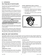
THERMOSTAT KNOB STOPPER

Each thermostat is equipped with a mechanical stop that can be
locked or unlocked with use of a screwdriver to prevent
temperatures in excess of that desired by the user; see Figure 4.
The maximum setting can be adjusted by loosening the screw "A"
and turning the stopper dial to desired maximum setting. Lock the
setting by tightening the screw. The Mechanical stop is under the
knob. Ensure that the knob is stopping at the correct position when
the knob is rotated clockwise from a lower temperature position.
(See Thermostat Adjustment.)

NOTE

To eliminate error due to piping heat losses,
measure pool temperature with an accurate
thermometer directly at the pool or spa.

THERMOSTAT ADJUSTMENT

The knob with locking feature eliminates the need for constant
thermostat adjustments. Set the knob pointer to the desired pool
or spa temperature.
If further adjustment is needed, rotate the knob until the desired
temperature is obtained. This knob position corresponding to
your desired maximum pool or spa temperature may now be
preset (locked) by the knob stopper which prevents the knob
from being turned beyond the maximum temperature you set.

Figure 4.

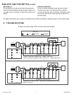
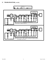
INDICATOR LIGHT DESCRIPTION

The MiniMax Pool Heater provides nine status indicator lights, six can be seen from the front of the control panel which help you
understand the operation of the heater. If something should go wrong, the lights will aid in troubleshooting the problem. Three
additional lights can be seen after opening the control panel. These three lights give the service technician advanced troubleshooting
capability. All the LED lights are green with the exception of the red service LED.

POWER LIGHT (POWER)

The light is on at all times, in any switch position, indicating 24
VAC power is being supplied to the control circuit. If it fails to
light, no other light will be on. Possible causes are: a) external
power to the heater is disconnected, check service panel circuit
breaker or fuses; b) local circuit breaker inside the transformer
has tripped -- investigate cause before resetting; c) transformer
has failed.

THERMOSTAT (TSTAT)

This light is on when the thermostat contacts close, signaled by
the water temperature falling below the setpoint, calling for the
heater to fire to maintain the desired water temperature.

AUXILIARY (AUX)

This light is on when it indicates the remote switch contacts are
closed. This allows you to observe if your remote switch is
properly closing the heater control circuit. When shipped from
the factory a jumper is installed to maintain closed circuit in the
absence of a remote switch.

PRESSURE (PRESS)

This light is on when Spa/Pool Selector switch is on, indicates
the circulation pump is running properly. If pressure light fails
to light, the pump may have lost its prime or water flow may be
restricted by an inadvertently closed valve or clogged filter or
pump basket. If you have determined that there is no water
flow restriction to the heater, you should call a qualified
serviceman.

POWER (THERMOSTAT SELECT) SWITCH

The Pool/Off/Spa switch allows the heater to be turned off
when heating is not desired.

1. “Pool” position - Maintains selected pool temperature.
2. “Off” position - Heater will not come on regardless

of drop in pool or spa temperature.

3. “Spa” position - This allows separate control of spa

water temperature.

Summary of Contents for 472099

Page 1: ...d in pool spa heater installation and maintenance If you do not follow these instructions exactly a fire or explosion may result causing property damage personal injury or loss of life For additional free copies of these instructions call 800 831 7133 Important Notice Attention Installer This manual contains important information about the installation operation and safe use of this product This i...

Page 2: ...HITE TERMINAL HOUSING 18 MALE TERMINAL FEMALE TERMINAL B WIRES IDENTIFICATION Thefollowingitemsarenewwireassembly providedinthekit A INSTALLATION 1 Turn off the electrical power to the heater 2 Open the heater s right door 3 Disconnectallwiresfromthe7800TemperatureControllerandtheIgnitionModule 4 Remove the left and right doors from the heater if necessary 5 Removesixscrewsontherearcoverofthe7800T...

Page 3: ...minal connect to F1 terminal of Ignition Module the other female terminal connect to Hot Surface Igniter HIS 2 h Connect new wire 4 orange The common female terminal connect to 24 VAC on the Fan Board the female terminal connect to PC on the Fan Board the male terminal connect to orange wire of P11 i Connect the new wires 5 white from F2 of Ignition Module to Terminal Block 4 j Install the In Line...

Page 4: ...INSTALLER MUST SUPPLY UL CSA APPROVED WIRE WITH 18 AWG 600V 105 C TEMP RATING ORG SW HL TFUSE J9 POOL SPA COM WHT WHT ORG WHT WHT GRN GRN OFF SPA J2 J3 THERMAL FUSE WIRING MUST BE REPLACED WITH INTERCONNECTING WIRING TO APPLIANCE MUST CONFORM TO THE NATIONAL ELECTRICAL CODE OR SUPERSEDE LOCAL WIRING CODES WHT WHT WHT WHT IF NO REMOTE SWITCH RED RED WHT BLK BLK WHT ORG BLU WHT BLK GRY ORG HIGH LIMI...

Page 5: ...L CSA APPROVED WIRE WITH 18 AWG 600V 105 C TEMP RATING O R G ORG SW HL TFUSE J9 POOL SPA COM WHT WHT ORG GRN GRN OFF SPA J2 J3 THERMAL FUSE WIRING MUST BE REPLACED WITH INTERCONNECTING WIRING TO APPLIANCE MUST CONFORM TO THE NATIONAL ELECTRICAL CODE OR SUPERSEDE LOCAL WIRING CODES WHT WHT WHT WHT IF NO REMOTE SWITCH RED RED WHT BLK BLK WHT ORG HIGH LIMIT 150 F 18 AWG 600V 150 C TEMP RATING ATTACH ...

Page 6: ... additional lights can be seen after opening the control panel These three lights give the service technician advanced troubleshooting capability All the LED lights are green with the exception of the red service LED POWERLIGHT POWER The light is on at all times in any switch position indicating 24 VAC power is being supplied to the control circuit If it fails to light no other light will be on Po...

Page 7: ...MT PRESS SRVE HI TEMP TFUSE GAS VALVE MV MV IGNITION MODULE IND GND VAL MV HEAT CLOSE IF NO MV THERMOSTAT RELAY REMOTE PRESS TFUSE HI TEMP LIMIT SWITCHES BREAKER CIRCUIT TRANSFORMER INCOMING LINE VOLTAGE THERMOSTAT CIRCUIT BOARD LIMIT SWITCHES HI TEMP NO MV CLOSE IF THERMOSTAT CIRCUIT BOARD TRANSFORMER LINE VOLTAGE INCOMING PWR CIRCUIT BREAKER TSTAT RMT RELAY THERMOSTAT REMOTE PRESS SRVE PRESS HI ...

Page 8: ...RMT REMOTE TRANSFORMER THERM INCOMING LINE VOLTAGE THERMOSTAT PWR BREAKER CIRCUIT TSTAT RELAY RMT REMOTE THERMOSTAT CIRCUIT BOARD NO MV CLOSE IF IGNITION MODULE SRVE HI TEMP LIMIT SWITCHES HI TEMP TFUSE MV IND TFUSE GND THERMOSTAT CIRCUIT BOARD GAS VALVE HEAT VAL MV MV IGNITION MODULE SRVE CLOSE IF NO MV HI TEMP LIMIT SWITCHES HI TEMP TFUSE MV IND TFUSE GND GAS VALVE HEAT VAL MV MV POWER SERVICE I...

Page 9: ...dges of the heater door can be sharp Handle heater door with care when trimming the plastic studs Failure to do so could result in lacerations from the heater door 2 Usingaknife slightlytrimtheplasticstud ifrequired andpushitthroughtheplasticbarrier Theninsertthe pushnuts included in the kit onto the plastic stud in order to hold the plastic barrier see Figure 5 SEALTHESE3SIDESWITHSILICON TRIMTHES...

Page 10: ...ousing 1 472059 Barrier Rain Shield 1 472060 Silicon Tube 1 472084 Label Wiring Diagram NT LN SVDS Model 400 Only 1 472086 Temperature Controller Assembly 6800 1 472088 Label Wiring Diagram NT LN SVSS Models 200 250 300 1 472091 Instruction Sheet 6800 Retrofit Kit 1 472094 Splice Self Stripping Electrical Tap Connector 1 472096 In Line Fuse 5 Amp 1 472103 Ignition Module 2466H 676 223 1 472104 Wir...

Page 11: ...Rev B 4 16 02 11 P N 472091 This page is blank ...

Page 12: ...P N 472091 12 Rev B 4 16 02 Pentair Pool Products Inc 1620 Hawkins Ave Sanford NC 27330 919 774 4151 10951 W Los Angeles Ave Moorpark CA 93021 805 523 2400 ...

Reviews: