


MAINTENANCE INSTRUCTIONS
43
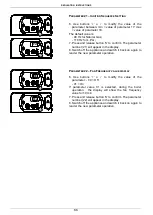
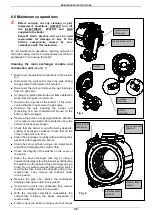
Circulating pump
(motor body) (see fig. 1)
Close the shut-off valves and drain the central
heating circuit of the boiler;
Use a
5 mm
Allen key to unscrew the four screws
securing the motor body to the impeller body;
Remove the motor body and check the condition of
the washer. If necessary, replace the washer;
Replace the circulation pump and re-assemble the
components following the above procedure in
reverse order;
Switch on the electricity, water and gas supplies and
fill the system with water. Check for any leaks from
the joints and bleed off any air from the circuit.
Restart the boiler.
Modulation circuit board
(see fig. 2-3)
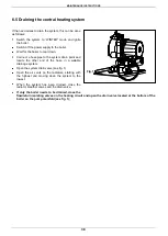
Open the control panel
(see 6.3 “Accessing the
boiler”);
Disconnect all the connectors, remove the
regulating knobs, unscrew the four fixing screws and
remove the modulation circuit board;
Replace the circuit board and re-assemble the
components following the above procedure in
reverse order;
Switch on the electricity, water and gas supplies
and regulate the boiler
(see
5.3 “Gas data”)
;
The preset parameters of the printed circuit
board correspond to an instantaneous type
boiler fed by natural gas.
When replacing the modulation circuit board,
check the “Minimum heating flow rate” –
Parameter 19 and “Max Heating power” –
Parameter 20.
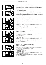
Electric fan circuit board
(see figs. 2-3)
Open the control panel
(see 6.3 “Accessing the
boiler”)
;
Disconnect the two connectors from the circuit board,
unscrew the two fixing screws and remove the board;
Replace the circuit board and re-assemble the
components following the above procedure in
reverse order;
Switch on the electricity, water and gas supplies.
electric fan circuit board
modulation circuit board
Fig. 3
circulating
pump
electric fan circuit board
modulation circuit board
Fig. 2
Fig. 1
Summary of Contents for PCH 18
Page 2: ......