background image

REGULATION  INSTRUCTIONS 


33 

P

ARAMETER 

21


I

GNITION 

S

EQUENCE 

S

ETTING


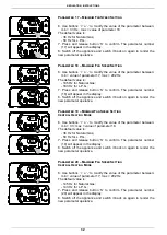
6.  Use  buttons  „+‟  o  „-‟  to  modify  the  value  of  the 

parameter between: min = value of parameter 17; max 
= value of parameter 18.  

The default value is: 
  - 90 Hz for Natural Gas; 
  - 110 Hz for L.P.G.; 
7

.


Press and release button „S‟ to confirm. The parameter 

number (21) will appear in the display. 

8. Switch off the appliance and switch it back on again to 
render the new parameter operative. 


P

ARAMETER 

22


F

AN 

F

REQUENCY VALUE DISPLAY 


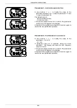
6.  Use  buttons  „+‟  o  „-‟  to  modify  the  value  of  the 

parameter: - 00 = Off  

  - 01 = On  
If  parameter  value  01  is  selected,  during  the  boiler 

operation,    the  display  will  show  the  fan  frequency 
value for 10 min.  

7. Pre

ss and release button „S‟ to confirm. The parameter 

number (22) will appear in the display. 

8. Switch off the appliance and switch it back on again to 
render the new parameter operative. 

P 21

S

S

S

S

110

00

P 22

110V   60Hz

110V   60Hz

110V   60Hz

110V   60Hz

Summary of Contents for PCH 18

Page 1: ...DIGITECH ENGLISH Instruction Manual for model PCH 18 Wall mounted heat only boiler Premix condensing system boiler This appliance must be installed by a licensed and or qualified technician Failure to properly install this appliance could result in property damage and possible injury or death to occupents ...

Page 2: ......

Page 3: ...1 Reference standard 10 3 2 Unpacking 11 3 3 Installing the boiler 12 3 4 Water connections 13 3 5 Condensate drain 15 3 6 Gas connection 16 3 7 Electrical connections 17 3 8 Flue connections 19 4 Commissioning the appliance authorized personnel 4 1 General warnings 20 4 2 Filling the system 21 4 3 Flushing the system 22 4 4 Filling the condensate trap 22 4 5 Starting up the boiler 23 5 Regulating...

Page 4: ...al warnings 34 6 2 Boiler inspection 34 6 3 Accessing the boiler 35 6 4 Flushing out the primary side 35 6 5 Draining the central heating system 36 6 6 Maintenance operations 37 6 7 Wiring diagrams 43 6 8 Troubleshooting 49 6 9 Diagnostics 50 6 10 Parts list 51 ...

Page 5: ...d must be disposed of in a responsible manner Before carrying out any cleaning or maintenance operations disconnect the appliance from the mains electricity supply by switching off at the main switch and or any other isolating device Do not obstruct the air intake or flue exhaust pipes Do not obstruct the air intake or flue exhaust terminals In the case of a fault and or malfunction in the applian...

Page 6: ...domestic power supply must be checked by a qualified electrician to ensure that it can support the maximum power absorption of the appliance as indicated on the appliance data plate positioned on the inside of the front casing In particular make sure that the cable ratings are adequate for the power absorbed Do not use adapters multiple sockets or extension leads to connect the appliance to the ma...

Page 7: ... simplicity the wall mounted appliance is equipped with all the appropriate accessories required to make it a fully independent boiler capable of satisfying central heating needs All boilers are fully inspected and are accompanied by a quality certificate signed by the inspector and a guarantee certificate This manual must be kept in a safe place and must accompany the boiler at all times Pensotti...

Page 8: ...104 Max heating working temperature C F 80 176 Expansion vessel capacity litres gal 6 1 60 Max working pressure heating bar psi 2 1 30 Min working pressure heating bar psi 0 3 4 29 Dimensions Boiler casing size Width in 16 1 Height in 28 7 Depth in 11 2 Weight net lb 16 36 Hydraulic connections Central Heating Flow connection NPT 3 4 Central heating Return connection NPT 3 4 Cold water mains conne...

Page 9: ...S 5 HR G CWI HF 5 9 1 9 3 1 4 1 2 0 98 30 1 9 12 3 1 9 4 4 7 3 4 4 1 2 16 1 4 2 5 5 6 4 11 2 5 2 11 2 28 7 4 1 HR G CWI HF 2 2 Dimensions LEGEND HR HEATING RETURN Ø3 4 HF HEATING FLOW Ø3 4 CWI COLD WATER INLET Ø1 2 G GAS Ø1 2 ...

Page 10: ...FETY THERMOSTAT 9 VENTURI 10 FAN 11 AUTOMATIC AIR VENT VALVE 12 PUMP 13 SAFETY VALVE 3 4 14 SYSTEM DRAIN VALVE 15 AUTOMATIC BY PASS 16 AIR PRESSURE SWITCH 17 EXPANSION VESSEL 18 IGNITION TRANSFORMER 19 IGNITION ELECTRODE 20 ELECTRONIC GAS VALVE 21 ROOM SEAL CHAMBER BACK SIDE 22 LOW WATER CUT OUT SWITCH 23 CONDENSATE TRAP 24 NO RETURN VALVE 25 WATER PRESSURE GAUGE 26 FILLING TAP 13 22 15 21 6 23 12...

Page 11: ...ENT VALVE 12 PUMP 13 3 BAR PRESSURE RELIEF VALVE 14 AUTOMATIC BY PASS 15 SYSTEM DRAIN VALVE 16 FLUE HOOD 17 IGNITION TRANSFORMER 18 IGNITION ELECTRODE 19 VENTURI 20 ROOM SEAL CHAMBER BACK SIDE 21 WATER PRESSURE SWITCH 22 CONDENSATE TRAP 23 CONDENSATE DRAIN PIPE 24 FLOW LIMITER 25 WATER PRESSURE GAUGE 26 NO RETURN VALVE 27 FILLING TAP LEGEND HR HEATING RETURN HF HEATING FLOW G GAS CWI COLD WATER IN...

Page 12: ...INSTALLATION INSTRUCTIONS 8 2 5 Circulation pump head flow graph Pump head I II III Pump speed Boiler losses I II III 0 5 10 15 20 25 30 0 2 4 6 8 10 Water flow US gpm Head ft ...

Page 13: ...cy indicator Temperature display When the boiler is switched off at the switch on the control panel the word OFF appears on the display The central heating frost protection system nevertheless remain enabled If the boiler was previously on it is switched off and the post ventilation circulation pump and protection functions are enabled The remote control where fitted remains active and illuminated...

Page 14: ...ove norms could lead to prosecution It is in the interest of the installer and safety that the law is complied with The manufacturers instructions form an integral part of the installation and should be left with the appliance but do not over ride in anyway statutory obligations Boiler room Installation requirements Please refer to local and national standards in force in the Country of destinatio...

Page 15: ...a potential hazard A Place the packed appliance on the floor see fig 1 making sure that the up arrow is facing down Remove the staples and open out the four flaps of the box B Rotate the boiler 90 while manually supporting it from underneath C Lift the box and remove the protections Lift the boiler by grasping the rear part and proceed with the installation STORAGE HANDLING Please note that prior ...

Page 16: ...necessary clearances indicated in figure 1 are respected To make the installation easier the boiler is supplied with a template to enable the pipe connections to be positioned prior to fixing the appliance to the wall To install the boiler proceed as follows see fig 2 a Use a level of not less than 24 long to mark a horizontal line on the wall where the boiler is to be fitted b Position the top of...

Page 17: ...talled above a gas meter regulator within F from the center line of the meter regulator G 48 Minimum clearance to service regulator vent outlet gas meter or electrical meter H 12 Clearance to non mechanical inlet air opening into the building I 36 Clearance to a mechanical air inlet into the building J 84 Minimum distance above a paved sidewalk or driveway located on public property If terminal is...

Page 18: ...nstallation the boiler is supplied with an hydraulic connection kit see fig 2 A pressure relief valve is installed in this dual purpose water heater that is rated in accordance with and complying with either The Standard for relief Valves and Automatic Shutoff Devices for Hot Water Supply Systems AINSI Z21 22 or The ANSI ASME Boiler and Pressure Vessel Code Section IV Heating Boilers The relief va...

Page 19: ...is often either partially or fully drained The outlet connection of the boiler safety valve must be connected to a discharge trap The manufacturer will not be held responsible for flooding caused by the operation of the safety valve in the case of system overpressure Condensate Drain The condensate drain flexible pipe supplied with the boiler conforming to UNI EN 677 standard must be connected to ...

Page 20: ...boiler is fitted in an unheated location the entire condensate discharge pipe should be treated as an external run 9 In alI cases discharge pipe must be installed to aid disposal of the condensate T o reduce the risk of condensate being trapped as few bends and fittings as possible should be used 10 When discharging condensate into a soil stack or waste pipe the effects of existing plumbing must b...

Page 21: ...r to boiler and comply with current standards and regulations Check the internal and external seals of the gas supply system A gas shut off valve must be installed upstream of the appliance Before starting up the boiler make sure that the type of gas corresponds to that for which the appliance has been set up see gas type label inside the boiler The gas supply pressure must be between the values r...

Page 22: ...connection to the mains electricity supply must be via a single pole switch with at least 0 1 inches gap between open contacts mounted upstream of the appliance Make sure that the positions of the live and neutral wires correspond to the wiring diagram Ensure the domestic power supply is checked by a qualified electrician to ensure that it can support the maximum power absorption of the appliance ...

Page 23: ...nect the wires to the terminal board B as follows Connect the earth wire normally coloured green yellow to the terminal marked with the earth symbol Connect the neutral wire normally coloured blue to the terminal marked with the letter N Connect the live wire normally coloured brown to the terminal marked with the letter L Terminals identified by the letters Ta Room thermostat Se Outside temperatu...

Page 24: ...1 In the case where a horizontal coaxial system is installed the coaxial terminal must be positioned horizontally in that the exhaust duct has been specifically designed with the required slope and the air intake has been suitably protected against the weather Concentric Flue connections It is mandatory that the manufacturers venting system be used Use only materials listed below for vent pipe and...

Page 25: ...he 2 4 to 3 15 5 test port adapter and the first 90 elbow are not included in the total equivalent length of the vent system Vertical venting systems The vent termination is not included in the total equivalent length of the vent system Horizontal venting systems must be sloped back towards the boiler at approximately per linear foot of vent Horizontal vent termination must terminate a minimum of ...

Page 26: ...th wires are connected properly Also make sure that the earth connection is sound Check the seals on the gas supply pipe from the mains and make sure that the meter does not register any flow of gas Test for gas soundness Check that the gas supply is correctly sized for the flow rate required by the boiler and that it is fitted with all the safety and control devices as lay down by current regulat...

Page 27: ...flow out of the radiators close the air vents Use the pressure gauge M fig 2 to check that the system pressure reaches 1 bar and that the code H2O does NOT appear on the control panel display see 2 7 section Control Panel If after the above operations there is a reduction in the pressure re open the filling tap R until the pressure gauge reads 1 bar and that the code H2O disappears on the control ...

Page 28: ...and repeat for all radiators on the system e Turn off the filling loop and close the drain cock open all radiators and open the filling to fill the system f Continue to fill the system until the pressure gauge reaches 14 5 psi 1 bar 4 4 Filling the condensate trap The condensation trap must be pre filled when starting the boiler for the first time in order to prevent flue gases from flowing back t...

Page 29: ...tes before re attempting to light the boiler To reset the boiler Switch off switch 1 see 2 7 Control Panel and switch it back on again and repeat the lighting procedure With the boiler ignited if the system still emits noises the operations must be repeated until all the air has been removed Check the pressure in the system If the pressure has fallen re open the filling tap until the code H2O disa...

Page 30: ...01 02 03 Atmospheric not premix Premix 25 kW Premix 29 34 kW Premix 50 kW 15 2 Zone management board activation 00 01 Off On 16 3 Telephone control activation 00 01 Off On 17 Minimum fan speed setting 38 Hz Natural Gas 50 Hz L P G To set the minimum frequency value Hz for the fan operation 18 Maximum fan speed setting 185 Hz Natural Gas 183 Hz L P G To set the maximum frequency value Hz for the fa...

Page 31: ...f switch while keeping buttons and pressed Wait for P 00 to appear on the display 3 Release buttons and 4 Keep button S pressed and use button and to select the parameter to modify 5 Release button S then re press and release it The display will indicate the value of the parameter to modify Adjust the value of the parameter using the procedure described in the following pages P00 S S S S O FF P00 ...

Page 32: ...SUPPLY 6 Use buttons and to modify the value of the parameter 00 natural gas 01 lpg 7 Press and release button S to confirm The parameter number 2 will appear on the display 8 Switch off the appliance and switch it back on again to render the new parameter operative PARAMETER 3 CENTRAL HEATING TEMPERATURE 6 Use buttons and to modify the value of the parameter 00 standard 86 176 F 01 reduced 77 104...

Page 33: ...arameter operative PARAMETER 5 WATER HAMMER PREVENTION Not applicable PARAMETER 6 CENTRAL HEATING TIMER 6 Use buttons and to modify the value of the parameter within the prescribed limits 00 0 x 5 0 90 90 x 5 450 7 5 min The default value is 36 180 3 min 7 Press and release button S to confirm The parameter number 6 will appear on the display 8 Switch off the appliance and switch it back on again ...

Page 34: ...ameter operative PARAMETER 8 D H W PUMP OVERRUN TIMER Not applicable PARAMETER NO 9 MINIMUM GAS PRESSURE SETTING Not applicable for premix burner only for atmospheric burner PARAMETER NO 10 MINIMUM CENTRAL HEATING OUTPUT SETTING Not applicable for premix burner only for atmospheric burner PARAMETER NO 11 MAXIMUM GAS PRESSURE AND MAX CENTRAL HEATING OUTPUT SETTING Not applicable for premix burner o...

Page 35: ...led to control the zone valves Then set the parameter at 01 7 Press and release button S to confirm The parameter number 15 will appear on the display 8 Switch off the appliance and switch it back on again to render the new parameter operative PARAMETER 16 TELEPHONE CONTROL 6 If a telephone interface is installed enable the board by setting parameter 16 at 01 7 Press and release button S to confir...

Page 36: ... the new parameter operative PARAMETER 19 MINIMUM FAN SPEED SETTING CENTRAL HEATING MODE 6 Use buttons o to modify the value of the parameter between min 33 max value of parameter 18 The default value is 38 Hz for Natural Gas 50 Hz for L P G 7 Press and release button S to confirm The parameter number 19 will appear in the display 8 Switch off the appliance and switch it back on again to render th...

Page 37: ...ppliance and switch it back on again to render the new parameter operative PARAMETER 22 FAN FREQUENCY VALUE DISPLAY 6 Use buttons o to modify the value of the parameter 00 Off 01 On If parameter value 01 is selected during the boiler operation the display will show the fan frequency value for 10 min 7 Press and release button S to confirm The parameter number 22 will appear in the display 8 Switch...

Page 38: ... gas pressure mbar psi 20 0 29 37 0 53 Consumi 59 F 14 5 psi ft 3 hr 67 44 25 71 Heating Power kW Fan frequency Hz diagram Table no 1 CO2 Values Gas type CO2 Natural gas G20 9 1 Liquid Propane Gas G 31 10 1 Table no 2 Frequency Gas type PARAMETER 17 19 Minimum Hz PARAMETRO 20 Maximum Central Heating Hz PARAMETER 18 Maximum D H W Hz Natural gas G20 38 145 185 Liquid Propane Gas G 31 50 143 183 ...

Page 39: ...llows Select the new gas type by changing parameter no P02 see Parameters table 5 2 Set the frequency value for the fan operation through parameters 17 18 19 20 according to Table 2 paragraph 5 3 for 18kW models only Unscrew the aluminium plug and insert the analyser in the exhaust sampling point PF see fig 1 paragraph 4 5 to check the CO value Make sure that the value complies with that reported ...

Page 40: ... in line with section Commissioning the boiler Remove and clean any oxidation from the burner Check that the seal of the room sealed chamber is undamaged and positioned correctly Check the primary heat exchanger and clean if necessary Check the maximum and minimum modulation pressures and the modulation itself Check the condition and operation of the ignition and gas safety systems If necessary re...

Page 41: ...nd right control panel support brackets see fig 5 and pull them outwards at the same time rotating the panel downwards Unscrew the four fixing screws see fig 6 and remove the panel back piece 6 4 Flushing out the primary side Fill the boiler as per the filling instructions Using a drain off cock on the lowest point of the system allow the water to drain from the system and boiler In order to flush...

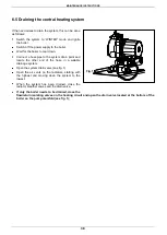
Page 42: ...in point and locate the other end of the hose in a suitable drainage system Open the system drain valve see fig 1 Open the air vents on the radiators starting with the highest and moving down the system to the lowest When the system has been drained close the radiator breather valves and the drain valve If only the boiler needs to be drained close the flow return isolating valves on the heating ci...

Page 43: ... attention not to remove the ceramic fibre protection from the bottom of the heat exchanger Check that the burner is not affected by deposits scaling or excessive oxidation Check that all the holes in the burner are free Clean the electrodes carefully without altering their positions with respect to the burner Clean the burner cylinder using a non metal brush and without damaging the ceramic fibre...

Page 44: ...he wires and re assemble the components following the above procedure in reverse order Switch on the power supply and restart the appliance If the boiler does not restart check the positions of the electrodes especially the ignition electrode Make sure that original position and distances between the electrodes and the burner are respected to avoid a boiler malfunction POSITIONING THE IGNITION ELE...

Page 45: ...ral heating circuit Then restart the appliance remembering to discharge any air that may be trapped in the system Gas valve see fig 3 Disconnect the joints and remove the gas pipe connecting the gas valve to the venturi Disconnect the gas feed pipe and valve ring nut at the bottom of the room sealed chamber Remove the flanged elbow coupling of the existing valve and fit it to the new valve also fi...

Page 46: ...n reverse order Switch on the electricity water and gas supplies and check the soundness of the joint by measuring the CO2 levels Expansion vessel see fig 2 Close the shut off valves and drain the central heating circuit of the boiler Use a 19 mm spanner to unscrew the pipe coupling to the vessel Unscrew the fixing screws and remove the upper mounting bracket Remove the expansion vessel from the f...

Page 47: ...fixing screws and remove the modulation circuit board Replace the circuit board and re assemble the components following the above procedure in reverse order Switch on the electricity water and gas supplies and regulate the boiler see 5 3 Gas data The preset parameters of the printed circuit board correspond to an instantaneous type boiler fed by natural gas When replacing the modulation circuit b...

Page 48: ...urn pipes Remove the support brackets and pull out the heat exchanger Remove the regulation sensor from the old heat exchanger and refit it together with the two condensate drainpipes to the new one Replace the heat exchanger and re assemble the components following the above procedure in reverse order Switch on the electricity water and gas supplies and fill the system with water Check for any le...

Page 49: ... blue black orange light blue black black brown brown brown orange orange black red black white light blue brown light blue light blue orange orange brown light blue brown fusibile 2A yellow green LN EXHAUST FAN type RG 128 PRINTED CIRCUIT BOARD DIGITECH SM20021 PRINTED CIRCUIT BOARD KOND DT SK11003 COD 76702LA M5 M1 M2 M3 M6 M7 M9 M10 M8 M4 C TS TF IG SR SS EV1 EV2 SE brown Storage cylinder timer...

Page 50: ...s When the wires have been connected place plate A back to position and then the front case panel Connecting the outside temperature sensor Option Connect the wires to the terminal board inside the instrument panel as follows a switch off the power supply at the main switch b remove the front case panel of the boiler c slacken the screws and remove plate A see fig 1 d connect the outside temperatu...

Page 51: ... temperature sensor on contacts marked as SE SE on the terminal board B When the wires have been connected place plate A back to position and then the front case panel Connecting the remote controller and the telephone control option Connect the wires to the terminal board inside the instrument panel as follows a switch off the power supply at the main switch b remove the front case panel of the b...

Page 52: ...ERM Zone valve management option remote controller board Remote control and zone valves wiring For the installation of a zone valve p c b it is necessary to access the main p c b for electrical connection see 6 3 Accessing the boiler and to activate the parameter no 16 see 5 1 Parameters table ...

Page 53: ...N INSTRUCTIONS 49 REMOTE OPEN THERM Telephone control Terminal block Outside temperature sensor option Zone valve management option remote controller board Remote control zone valves and telephone control wirings ...

Page 54: ...rrection is reported in figure 1 The selection of the compensation curve is determined by the maximum delivery temperature Tm and the minimum outdoor temperature Te N B The y axis values of the delivery temperature Tm refer to standard 176 86 F appliances or 104 77 F floor mounted appliances The type of appliance can be programmed using parameter 3 see 5 1 Parameter programming 55 OUTDOOR SENSOR D...

Page 55: ...SPECT AND CLEAR OBSTRUCTION f REROUTE HOSE EMPTY CONDENSATE g REPLACE FAN PROVER SWITCH h CHECK CONNECTIONS RESECURE TO TERMINALS i REPLACE WIRES E03 FLUE SAFETY THERMOSTAT a THERMOSTAT BROKEN b THERMOSTAT CABLE DICONNECTED c THERMOSTAT LOCK OUT HIGH FLUE TEMPERATURE DIRTY HEAT EXCHANGER d LOW WATER FLOW THROUGH HEAT EXCHANGER a REPLACE PART b CHECK THE ELECTRICAL CONNECTION c RESTART AND CHECK TH...

Page 56: ...test function Pressing the boiler off button deactivates the function The Flue test function operates the boiler at the maximum heating pressure for 15 minutes without any modulation The function is useful for combustion testing 08 Frost Protection Central heating circuit The function is activated when the heating sensor senses a temperature of 5 C The boiler operates at minimum gas pressure with ...

Page 57: ... AIR PRESSURE SWITCH 2 14 UL CSA 35031LA IGNITION ELECTRODE 35032LA IONISTATION ELECTRODE 36068LA VENTURI MINIFOLD 36075LA GAS VALVE UL CSA 37033LA FAN PX 2065 UL CSA 59015LA WATER PRESSURE SWITCH PC 5411 BRASS 73516LA HTG CLIP SENSOR FOR PIPE 17 18 mm BLUE T7335D1123B 73517LA THERMO FUSE 102 C RED ISOTHERM 1 4 4X45 76702LA PRINTED CIRCUIT BOARD KOND DT SK11003 76719LA MAIN PRINTED CIRCUIT BOARD U...

Page 58: ...Pensotti North America 34 Coffin Ave Brewer ME 04412 P 207 942 3636 F 207 942 3737 www pensotti pna com ...

Reviews: