background image

17

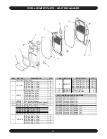
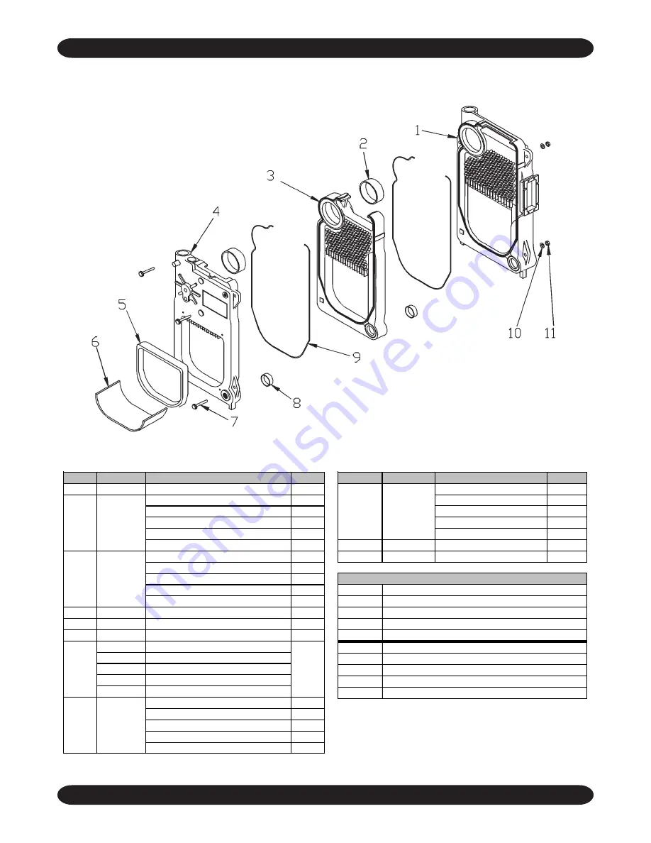
REPLACEMENT PARTS - HEAT EXCHANGER

ITEM

PART NO.

DESCRIPTION

QTY

1

100-5-10.01 Rear Section

1

#60 Push Nipple - 3 Sec.

2

#60 Push Nipple - 4 Sec.

3

#60 Push Nipple - 5 Sec.

4

#60 Push Nipple - 6 Sec.

5

#60 Push Nipple - 7 Sec.

6

Center Section - 3 Sec.

1

Center Section - 4 Sec.

2

Center Section - 5 Sec.

3

Center Section - 6 Sec.

4

Center Section - 7 Sec.

5

4

10051202

Front Section Castover

1

5

5611508

Kit - Target Wall & Insulation Blanket

1

6

25511005

Insul Blanket 16x24 (6 & 7 Section)

1

HW-025.05 Tie Rod ½ x 9 - 3 Sec.
HW-025.01 Tie Rod ½ x 12½ - 4 Sec.
HW-025.02 Tie Rod ½ x 16½ - 5 Sec.
HW-025.03 Tie Rod ½ x 20½ - 6 Sec.
HW-025.09 Tie Rod ½ x 23½ - 7 Sec.

#22 Push Nipple - 3 Sec.

2

#22 Push Nipple - 4 Sec.

3

#22 Push Nipple - 5 Sec.

4

#22 Push Nipple - 6 Sec.

5

#22 Push Nipple - 7 Sec.

6

7

3

8

100-1-5.01

2

100-1-8.01

3

10051101

ITEM

PART NO.

DESCRIPTION

QTY

Rope, Med. Density - 3 Sec.

13.0'

Rope, Med. Density - 4 Sec.

19.5'

Rope, Med. Density - 5 Sec.

26.0'

Rope, Med. Density - 6 Sec.

32.5'

Rope, Med. Density - 7 Sec.

39.0'

10

HW-008.03

Washer ½ ID Flat

3

11

HW-003.05

Nut ½-13 Hex Head

3

10022201
10022202
10022203
10022207
10022208

10022204
10022205
10022206
10022209
10022210

9

MS-006.00

FULLY ASSEMBLED HEAT EXCHANGERS

7 Section With Tankless Coil

3 Section Without Coil

3 Section With Tankless Coil
4 Section With Tankless Coil
5 Section With Tankless Coil
6 Section With Tankless Coil

4 Section Without Coil
5 Section Without Coil
6 Section Without Coil
7 Section Without Coil

Summary of Contents for KEYSTONE STEAM II

Page 1: ...ND OPERATING INSTRUCTIONS P N 1305030 Rev 1 0 08 04 An ISO 9001 2000 Certified Company PENNCO BOILERS 85 Middle Rd Dunkirk NY 14048 Ph 716 366 5500 Fax 716 366 1209 www ecrinternational com MODEL NUMBERS KSB0365 KSB3100 KSB4125 KSB4150 KSB5175 KSB5200 KSB6225 KSB7275 ...

Page 2: ... in minor or moderate injury It may also be used to alert against unsafe practices IMPORTANT Read the following instructions COMPLETELY before installing WARNING 1 Keep boiler area clear and free from com bustible materials gasoline and other flam mable vapors and liquids 2 DO NOT obstruct air openings to the boiler room 3 Modification substitution or elimination of factory equipped supplied or sp...

Page 3: ...e KSB0365 0 65 91 78 59 246 68 6 8x8x15 140 60 80B 84 KSB3100 1 00 140 116 87 363 101 6 8x8x15 140 85 80B 81 5 KSB4125 1 25 175 145 109 454 126 7 8x8x15 140 1 10 80B 82 5 KSB4150 1 50 210 170 128 533 148 7 8x8x15 140 1 25 80B 81 KSB5175 1 75 245 202 152 633 176 8 8x8x15 140 1 50 80B H 83 KSB5200 2 00 280 227 170 708 197 8 8x8x15 140 1 75 70B H 82 KSB6225 2 25 315 251 188 783 218 3 8 8x12x15 140 2 ...

Page 4: ...e flooring Allow 24 inches in the front top and right hand side for servicing and cleaning or removing tankless water heating coil It is recommended that 24 inches be allowed in back of boiler for convenience when skimming hole is used When installed in a utility room the door should be wide enough to allow the largest boiler part to enter or to permit replacement of another appliance such as a wa...

Page 5: ...ollow orapplicable provisions of the local building codes 3 When the boiler is installed in an unconfined space in a building of unusually tight construction air for combustion and room ventilation must be obtained from outdoors or from spaces freely communicating with the outdoors A permanent opening or openings having a total free area of not less than 1 square inch per 5 000 BTU per hour of tot...

Page 6: ...y connect The minimum dimension of rectangular air ducts shall not be less than 3 inches 6 In calculating free area using louvers grills or screens for the above consideration shall be given to their blocking effect Screens used shall not be smaller than 1 4 inch mesh If the free area through a design of louver or grill is known it should be used in calculating the size opening required to provide...

Page 7: ...g information refer to the I B R installation piping guide FIGURE 5 3 See Figure 6 for typical piping for domestic hot water heater 4 See Figures 7 and 8 for the suggested piping for a modular steam boiler SUGGESTED PIPING FOR MODULAR STEAM BOILERS PUMPED RETURN FIGURE 7 PIPING FOR BUILT IN DOMESTIC HOT WATER HEATER FIGURE 6 SUGGESTED PIPING FOR MODULAR STEAM BOILERS GRAVITY RETURN FIGURE 8 ...

Page 8: ...chimney sloping upward continuously toward the chimney approximately 1 4 per foot Bolt or screw joints together to avoid sag If an oil fired water heater is vented into the same flue astheboiler provideaseparateholeintothechimney whenever possible When this isn t possible use a Y connection in the flue pipe using a separate draft regulator for each unit When a chimney will not provide adequate dra...

Page 9: ...ctrical Code ANSI NFPA No 70 and or local authority having jurisdiction 1 When an external electrical source is utilized the boiler when installed MUST BE electrically groundedinaccordancewiththeserequirements 2 Install a fused disconnect switch between boiler and meter at a convenient location 3 When the boiler is equipped with self ener gizedcontrols nooutsidesourceofelectricpower shall be conne...

Page 10: ...ergy Cut Off TH 3 Thermostat Line Voltage 1K Relay Coil PSC Pilot Safety Coil TR 1 Transformer 120V 24V 40VA 1K1 Relay Contacts Wire Connection TR 2 Transformer 120V 24V 50VA 1K2 Relay Contacts LWCO Low Water Cut Off LGV24 Volt Gas Valve LS Limit Switch EWF Electric Water Feeder PS Pressure Switch MS Manual Switch PG Power Generator WIRING CODE Line Voltage By Factory Low Voltage By Factory Line V...

Page 11: ... to the latest revision of the NFPA 211 The lever of the pressure relief valve Figure 12 on the boiler should be operated periodically to make sure that it is functioning properly WARNING Discharge will be boiling hot water and steam The pressure relief valve should open before the steam pressure exceeds the 15 lb reading on the gauge If this pressure is exceeded and the pressure relief valve leak...

Page 12: ...stat to call for heat or jump thermostat contacts on the boiler control E Open all oil line valves F Turn service switch on Burner should start G On one pipe fuel systems only bleed pump as soon as burner starts Allow oil to run until all traces of air in the suction line disappear H Turn OFF burner and install pressure gauge port on pump I Start burner again and check oil pressure for 140 lbs Adj...

Page 13: ...etely closed To remove soot and scale from the flueways remove top jacket panel top clean out plate open burner swing door Figure 12 OPENING THE BURNER SWING DOOR 1 Turnoffpowertoboilerandallowboilertocooldown 2 Disconnect power cable at factory supplied burner electrical disconnect Figure 12 3 Loosen screws on the sides of the lower front jacket panel Figure 6 Pull the bottom part of the lower fr...

Page 14: ...she should also clean or replace air vents and traps clean flue passages and check for proper operation of all controls and safety devices The venting system should be inspected at the start of each heating season Check the vent pipe from the boiler to the chimney for signs of deterioration by rust or sagging joints Repair if necessary Impuritiesinboilerwaterofasteamboilermaycause foaming and an u...

Page 15: ...oiler and boiler room must not be restricted or blocked Periodic inspection and tightening of the tankless heater cover plate bolts will reduce the risk of leaks See parts 3 and 5 under Coil and Cover Plate Replacement Parts MECHANICAL LOW WATER CUT OFF Operation should be checked with burner on by opening the blow off valve located in the lower portion of the low water cut off body This will drai...

Page 16: ...eckett Riello 28511801 Harness Aquastat 41 Carlin 1263013 Burner Harness 8 Beckett 1263011 Burner Harness 8 Riello 28511901 Burner Harness 8 Carlin This includes MLWCO 2 4 5 7 8 9 10 6 11 1 12 1 REPLACEMENT PARTS HARDWARE ITEM PART NO DESCRIPTION QTY 1 VR 002 02 Relief Valve 15 1 2 PF 019 02 Pipe Fit Coupling 1 3 PF 005 01 Pipe Fit Npl Close 1 4 HW06701 Stud 5 16 18 x 2 3 8 4 5 2252501 Support Jac...

Page 17: ...23 7 Sec 22 Push Nipple 3 Sec 2 22 Push Nipple 4 Sec 3 22 Push Nipple 5 Sec 4 22 Push Nipple 6 Sec 5 22 Push Nipple 7 Sec 6 7 3 8 100 1 5 01 2 100 1 8 01 3 10051101 ITEM PART NO DESCRIPTION QTY Rope Med Density 3 Sec 13 0 Rope Med Density 4 Sec 19 5 Rope Med Density 5 Sec 26 0 Rope Med Density 6 Sec 32 5 Rope Med Density 7 Sec 39 0 10 HW 008 03 Washer ID Flat 3 11 HW 003 05 Nut 13 Hex Head 3 10022...

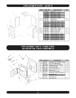
Page 18: ...l 1 21521803 Left Side Panel 3 Sec 21521804 Left Side Panel 4 Sec 21521805 Left Side Panel 5 Sec 21521806 Left Side Panel 6 Sec 21521807 Left Side Panel 7 Sec 7 1 1 1 3 1 REPLACEMENT PARTS SWING DOOR AND MOUNTING DOOR COMPONENTS ITEM PART NO DESCRIPTION QTY 1 2552901 Mounting Door Insulation Plug 1 1a 2551901 Door Plug Replacement 1 2 HW 005 01 Screw 20x Self Tapping 2 3 10011701 Observation Door ...

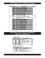
Page 19: ...0B KSB5200 Beckett NZ01201 Nozzle 2 00 45B KSB6225 Beckett 14619346 Nozzle 2 25 45B KSB7275 Beckett NZ00802 Nozzle 85 80W KSB3100 Riello 1320012 Nozzle 1 10 60W KSB4125 Riello NZ00804 Nozzle 1 25 60W KSB4150 Riello NZ00206 Nozzle 1 75 80B KSB5200 Riello 1320002 Nozzle 85 70B KSB3100 Carlin 1320010 Nozzle 1 10 70B KSB4125 Carlin NZ00904 Nozzle 1 25 70B KSB4150 Carlin NZ00905 Nozzle 1 75 70B KSB5200...

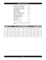
Page 20: ...ce X Inspect Oil Line Size Leaks X Inspect Electrical Connections X Install New Filter X Room Make up Air X Electrode Setting X Proper Light Off Hot Cold X Controls and Safety Devices X Nozzle Size Angle Type Pump Pressure Vacuum Line Voltage Motor Amps Smoke Test Draft Overfire In Flue CO2 or O2 Flue Gas Temperature Measure with instruments and record results below ...

Reviews: