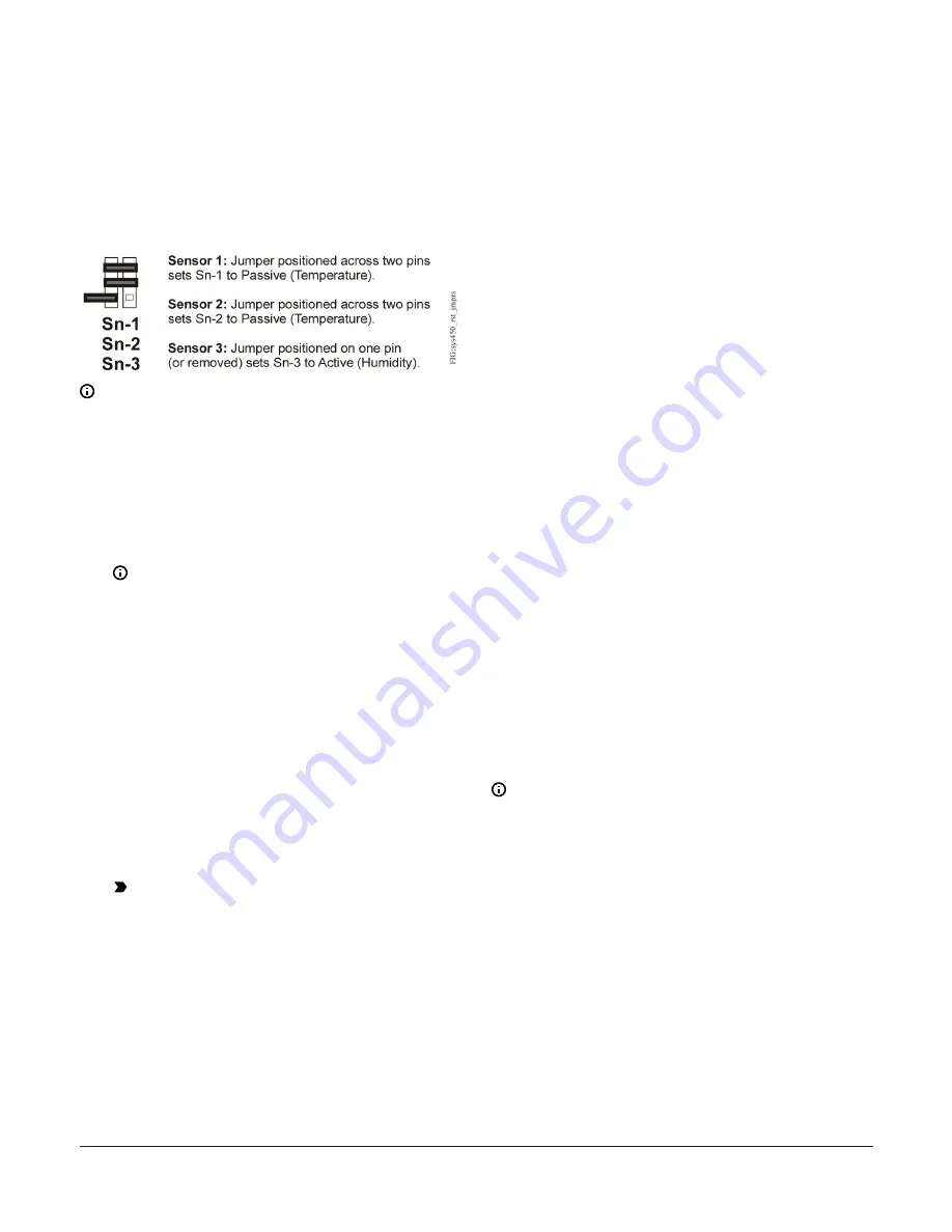
Temperature sensors are passive (2-wire) sensors and the
corresponding jumpers must be positioned across both
pins. Humidity transducers are active (3-wire) sensors and
corresponding jumpers must be positioned on one pin (or
removed completely).
Figure 5 shows the jumper positions for the System 450
Reset Control example shown in Figure 3.
Figure 5: Active/Passive sensor jumper positions for
System 450
Note:
Jumpers are only present in Version 1.
Setting up a control system in the UI
System 450 control modules have a backlit LCD and a
four-button touch pad UI (Figure 4) that enable you to set
up your control system.
1.
Build your control system module assembly and
connect it to power. See
Note:
Every time a module assembly is
powered ON, the control module polls all of
the modules to identify output type (relay
or analog) and assigns a sequential output
number (1 to 9 [0 = 10]) to each output starting
with the control module output on the left. The
output numbers identify each output’s setup
screens in the UI. (See Figure 4.)
2.
Access the System 450 setup screens in the UI. See
Accessing the System 450 Setup screens
3.
Set up the control system sensors (inputs) in the UI.
See
.
4.
Set up the control system outputs in the UI. See
5.
Set up the clock and occupied/unoccupied schedule
in the UI for systems that use setback. See
.
Important:
- When power is disconnected, the time
clock keeps time for 12 hours before
resetting to default; the remaining setup
values entered into the UI remain in non-
volatile memory indefinitely.
- Do not change the module positions
after a System 450 control system is set
up in the UI. System 450 control logic is
set up in the UI according to the Sensor
Types, the output types, and the output
numbers. Changing modules or module
positions in a module assembly that is
already set up in the UI, can change the
output numbers, output types, and the
setup values of the assembly outputs,
which requires setting up the outputs
again.
See Figure 4 for an explanation of the System 450 display
screen and the 4-button touch pad features and functions.
See Table 3 for Reset Control Sensor Types and associated
sensors. See
through
Relay Output and Analog Output that reference the
for System 450 UI setup information and
procedures.
Viewing the Main and System Status
screens
After you install, wire, power on, and set up your control
system in the UI, the Main screens appear on the LCD.
During normal operation, the Main screens automatically
scroll through the current status of each sensor in your
control system, the time and day, and the current Reset
Setpoint value.
The System Status screens display the current status of
each output in your control system and the runtime hours
for each Output Relay. In the Main screen, press
Next
repeatedly to scroll through and view all of the Main and
System Status screens in your control system.
During normal operation, the Reset Control Main screens
automatically scroll through the current temperature or
humidity sensed at each sensor, the current time and day,
and the current calculated Reset Setpoint (RSP) value. See
the Main Screens row in the setup screens flow chart in
.
Note:
• You must set up time and day of week for control
applications that use the setback feature, but you
can also set up time and day on control systems
that do not use the setback feature. If the time
and day have not been set up, the Time/Day
Status screen displays
– –:– –
,
MON
, and
AM
.
• Main screens are view-only; selections cannot be
made in Main screens.
During normal operation while the LCD is auto-scrolling
through the Main screens, press
Next
repeatedly to
scroll through and view the available System Status
screens. Press and hold
Up
and
Down
simultaneously
for 5 seconds to access the Setup Start screens and the
System 450 system setup screens.
In the following figure, the screen examples show Sensor
1 sensing 27°F outdoor air at the Master sensor, Sensor
2 sensing 151°F at the boiler water supply outlet, the
System 450 Series Reset Control Modules with Real-Time Clock and Relay Output Installation Guide
6


