Solaris 2
Sterilizaton CenterInstallation Manual
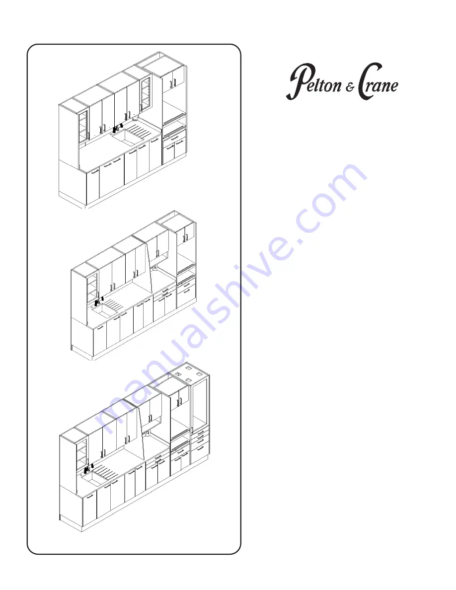
Model: SSC
8’ - SSC96-2-R
8’ - SSC96-2-L
10’ - SSC120-2-R
10’ - SSC120-2-L
ach Rules!
12’ - SSC147-2-R
12’ - SSC147-2-L
Page 1: ...Solaris 2 Sterilizaton Center Installation Manual Model SSC 8 SSC96 2 R 8 SSC96 2 L 10 SSC120 2 R 10 SSC120 2 L ach Rules 12 SSC147 2 R 12 SSC147 2 L ...
Page 2: ...ET BASE INSTALLATION 8 BACK PANELS TO CABINET INSTALLATION 9 HANGING RAIL INSTALLATION 13 ELECTRICAL STRIP INSTALLATION 15 UPPER STORAGE INSTALLATION 14 THREE SHELF STERILIZATION TOWER INSTALLATION 12 GENERAL ROUTING GUIDE 16 PLUMBING SCHEMATIC 18 LIGHT ELECTRICAL PNEUMATIC DOOR CONTROLS 19 ELECTRICAL STRIPS AND STERILIZER TOWER ELECTRICAL SCHEMATIC 20 FINAL ASSEMBLY ADJUSTMENT 21 Zach Rules TOWER...
Page 3: ...equired important to follow instruction Not a caution Warning strong magnetic field Off On Light Switch Mode of operation SSC Continuous Interference with Electromedical Devices To guarantee the safety of electromedical devices it is recommended that the operation of mobile radio telephones in the medical practice or hospital be prohibited Strong EMI sources such as electro surgery units or x ray ...
Page 4: ...4 PRODUCT IDENTIFICATION 1 013 2466 R00 ...
Page 5: ...5 Front View PREPARING THE SITE Side View 1 013 2466 R00 Zach Rules ...
Page 6: ...gs and not your back Make all required air water and drain attachments from the utilities to the incoming stub up connections before the system installation occurs Doing so prevents damage to the utility lines from heat associated with some plumbing connection methods To ensure proper operation of the unit flush air and water lines before connecting the equipment Turn main power OFF at the install...
Page 7: ...p Receptacles 120VAC 50 60hz 15A DC5 8 Sterilization Tower Receptacle 120VAC 50 60hz 15A Bottom Sterilization Tower Receptacle 120VAC 50 60hz 15A 2 circuits or Sterilization Tower Receptacle 230VAC 50 60hz 15A 2 circuits An additional 2 circuit Sterilization Tower Receptacle is supplied for 3 shelf towers four 4 120VAC 15 amp branch circuits or four 4 230VAC 15 amp circuits Typical Individual Circ...
Page 8: ... procedures with the technician facing the front of the cabinet Pull Tab WARNING Be sure the main power is turned off at the installation site WARNING Do not lift cabinets by their countertops 3 Remove false floors from the lower modules 4 Position sink cabinet base over the sink plumbing stub ups or stub outs 5 Level the module by turning the leveling feet Turn the leveling feet clockwise to lowe...
Page 9: ... D the same as panel A locking the cams as you go Frontside of panels Tighten Cams 4 Screw the bottom of the panels into wall studs 2 from the bottom 2 Place the end panel on the base using the locating pins Attach back panel A to the end panel using the locating pins Back panel will rest on the back of the lower cabinet Tighten the cams 1 3 clockwise using a 3 Phillips screwdriver 1 013 2466 R00 ...
Page 10: ...side of wrapping station Align the wrapping station holes with the tower holes 2 Using the 4 cabinet to cabinet connectors secure wrapping station module to tower 1 013 2466 R00 3 Secure tower to back panel INSTALLING THE TOWERS ...
Page 11: ... clean storage tower to the from the column in the back 1 013 2466 R00 sterilization tower Zach Rules 8 Level the module by turning the leveling feet Turn the leveling feet clockwise to lower and counterclockwise to raise the cabinet Ensure all modules are level across the top and that all of the leveling feet are making contact with the floor holes in the clean storage tower 4 Open the storage ca...
Page 12: ...m the kit that is provided with the tower unit 064140 MOUNTING HARDWARE MUST BE ATTACHED TO WOOD WALL STUD IN 2 PLACES USING 4190067 10 X 2 5 SCREWS AND 5439117 FLAT WASHERS OR THROUGH METAL STUDS USING 046114 TOGGLERS 056549 1 4 20 X 60MM FLAT HEAD SCREWS AND 3000705 FLAT WASHERS MUST BE ATTACHED THRU SHEETROCK IN 2 PLACES USING 046114 1 4 20 TOGGLER 056459 1 4 20 X 60MM FLT HD SCREWS AND 3000705...
Page 13: ...13 INSTALLING HANGING RAIL 1 Install hanging rail to back panel using screws provided 2 Fasten back panels to studs in wall for additional support Hardware not included 1 013 2466 R00 ...
Page 14: ...usly stated using eight of the cabinet to cabinet 8 The modules can now be adjusted in or out and up or down until level and plumb Start by adjusting bottom screw A clockwise until cabinets are pulled firm against back panel After all modules are firm against back 5 Position glass divider in between the first wrap station upper and the second upper after hanging the wrap upper and before hanging t...
Page 15: ... countertop screws provided Tighten securely 4 Route power strip wiring and power switch wiring through the cut out in electrical chase and through the base of cabinet 5 Install power strip into the cut out of the electrical chase Secure strip using the four 8 32 screws Tighten securely 3 Slide electrical chase inside Stage 1 and Stage 2 into the back panels Electrical chase with the on off 1 013 ...
Page 16: ...ck is located in the waste module Connect wiring for the on off sensor and the lights to the power pack Plug into an outlet in waste area 5 Optional Bump out waste drawer Plug power cable into outlet in the waste area 6 Optional Route the pneumatic door air lines and connect to the control box in the waste area 7 Route Air Q D tubing from the Q D connection in the electrical chase down into the su...
Page 17: ...the filtration system and the tank accessories manuals etc 2 Remove the filtration system and mount the VistaPureTM backer board inside the base cabinet of the wrap station as shown below using 4 wood screws 3 Refer to installation manual for VistaPureTM for making plumbing connections ...
Page 18: ...18 WATER AIR Faucets and HVE to be installed into countertop by plumber UTILITY AREA OPTIONAL VISTACLEAR SYSTEM PLUMBING SCHEMATIC 1 013 2466 R00 ...
Page 19: ...19 LIGHT ELECTRICAL PNEUMATIC DOOR CONTROLS 24DC POWER SUPPLY PNEUMATIC DOOR SOLENOID UNDER SINK MODULE 1 013 2466 R00 DC4 ...
Page 20: ...I outlets located in the waste module and the sink area that will be hard wired at the installation site to 120VAC 15 amp circuit ELECTRICAL STRIPS AND STERILIZATION TOWER ELECTRICAL SCHEMATIC Each receptacle on the duplex outlet s in the sterilization tower must be hard wired to individual 15 amp branch circuits A second receptacle will be supplied with the 3 shelf sterilization tower 120VAC OR 2...
Page 21: ...rawer FINAL ASSEMBLY ADJUSTMENT DYNAPRO ADJUSTMENT TIOMOS HINGE ADJUSTMENT VIONARO ADJUSTMENT KINVARO ADJUSTMENT 1 Re install all doors and drawers to their modules 1 013 2466 R00 2 Adjust doors using manufacturer s guidlines in the links below 3 Adjust drawers using manufacturer s guidlines in the links below Install side splashes with 100 silicone caulk seal seams 4 around sink backsplash chases...
Page 22: ...P N 1 013 2466 Rev 00 08 07 17 Printed in USA 2017 Pelton Crane 11727 Fruehauf Drive Charlotte NC 28273 USA We reserve the right to make any alterations which may be due to any technical improvements ...