background image

EN 9

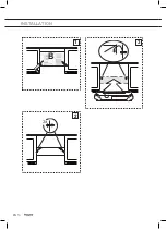
INSTALLATION

General

This appliance should be connected to the power supply by a 
recognized fitter who is familiar with, and works according to the 
correct safety regulations. This appliance meets the European 
requirements.

Important that you know:

•  The minimum distance between the supporting surface for the 

cooking vessels on the gashob and the lowest part of the range 
hood must be not less than 65 cm. For use with an electric, ceramic 
or induction hob, this distance must be at least 55 cm.

•  If the cooker hood is to be fitted to an existing duct no other 

appliances, such as a geyser or heater, may be connected to that 
same duct.

•  Consider local regulations with respect to the ventilation of gas 

appliances.

•  The shorter the duct, and the fewer the bends in it, the better the 

cooker hood will work.

•  Before you start drilling check that there are no installation cables 

present.

•  The connecting pipe for the cooker hood has a diameter of  

120 mm. It is best also to use a flue pipe of the same diameter.

•  The installation material supplied with this range hood is designed 

for fixing to reinforced concrete or masonry walls. For some types 
of walls you may need special plugs and screws.

Summary of Contents for MWA105KOR

Page 1: ...Gebruiksaanwijzing Afzuigkappen Mode d emploi Hotte cheminée Bedienungsanleitung Dunstabzugshaube Instructions for use Cooker hood MWA105KOR ...

Page 2: ... 3 FR 15 DE Bedienungsanleitung DE 3 DE 15 EN Instructions for use EN 3 EN 15 Gebruikte pictogrammen Pictogrammes utilisés Benutzte Piktogramme Pictograms used Belangrijk om te weten Important à savoir Wissenswertes Important information Tip Conseil Tipp ...

Page 3: ...ngselementen 6 Onderhoud Reiniging 7 Vetfilters verwijderen 8 Lampen vervangen 8 Installatie Algemeen 9 Elektrische aansluiting 10 Voorbereiding 11 Voor gebruik met een centraal afzuigsysteem 11 Voor gebruik met een externe motor 12 Montage 13 Bijlage Apparaat en verpakking afdanken 15 ...

Page 4: ...at U vindt hierin informatie over veiligheid en onderhoud van het apparaat Bewaar deze gebruiksaanwijzing evenals de installatiehandleiding Deze kunnen later van pas komen Beschrijving A B C 1 0 0 1 2 3 A Schuifknop voor verlichting B Indicatielampje C Schuifknop voor externe ventilator klep UW AFZUIGKAP ...

Page 5: ...te voeren naar het centrale systeem Klep openen sluiten en snelheid van het centrale afzuigsysteem regelen In de UIT stand bestaat er nog afzuiging via de kap vanwege een kleine opening in de klep Met de schuifknop in stap 2 3 gaat de centrale afzuigmotor dienovereenkomstig in de snellere stand Lees eerst de afzonderlijke veiligheidsinstructies voordat u het apparaat in gebruik neemt UW AFZUIGKAP ...

Page 6: ...erne motorventilator in of uitschakelen In stand 0 1 de externe motor werkt met snelheid één de klep wordt gesloten met open gat kleine klep in stand open voor basisventilatie van het centrale mechanische ventilatiesysteem Het indicatielampje is uit 1 Verplaats de schuifknop naar stand 2 of 3 De afzuigkap schakelt het centrale afzuigsysteem met de corresponderende snelheid Het indicatielampje gaat...

Page 7: ...rhoud of het niet navolgen van bovengenoemde aanbevelingen Afzuigkap Reinig de afzuigkap met een sopje en een zachte doek Neem daarna af met schoon water Gebruik geen agressieve schoonmaakmiddelen zoals soda Het af en toe in de was zetten van de lak zorgt voor een blijvend fraai uiterlijk van de afzuigkap Roestvrij stalen afzuigkappen Gebruik geen schuursponsjes of iets dergelijks Behandel het app...

Page 8: ...ichting Lampen vervangen De lamp in dit huishoudelijke apparaat is uitsluitend bedoeld voor verlichting van dit apparaat De lamp is niet geschikt voor de verlichting van een huishoudelijke ruimte Let op Haal eerst de stekker van het apparaat uit het stopcontact voordat de lampen worden vervangen 1 Verwijder de vetfilters 2 Dit geeft toegang tot de lampen 3 Schroef de lamp los uit de fitting en ver...

Page 9: ...moet worden op een bestaand kanaal mogen er geen andere toestellen zoals een geiser of een ander verwarmingstoestel aangesloten zijn op datzelfde kanaal Houd rekening met plaatselijke regelgeving met betrekking tot de ventilatie van gastoestellen Hoe korter het kanaal en hoe minder bochten hoe beter de afzuigkap werkt Controleer vóór het boren of er geen installatieleiding in de weg zit De aanslui...

Page 10: ...rden van de voeding overeenkomen met de waarden die op het gegevensplaatje op het apparaat zijn aangegeven U sluit het apparaat als volgt aan op het elektriciteitsnet BRUIN fase L stroomvoerend BLAUW fase N neutraal Let op Als u een vaste aansluiting wilt maken moet er in de voedingskabel een meerpolige schakelaar met een contactafstand van 3 mm worden geplaatst max 140 cm ...

Page 11: ...bereiding voor gebruik met een centraal afzuigsysteem en snelheidsregeling De snelheid wordt geregeld op de afzuigkap 1 Verwijder de vetfilters 2 Draai de kleine klep naar de stand open Draai zo nodig de montageschroef een beetje los 3 Draai de montageschroef vast om te voorkomen dat de kleine klep in de loop der tijd sluit ...

Page 12: ...geselecteerd zie hiervoor alleen de handleiding van de motorunit De diverse mogelijkheden worden vaak aangegeven als gemiddelde instelling of daginstelling hoge instelling of kookinstelling Bedradingsschema Led lamps Red VLT L B RED 1 2 3 4 5 6 7 8 9 10 3 4 5 6 BRW LIGHT 0 1 N F 220 240V 50Hz N F COM 1 V 2 V 3 V BRW L B BRW L B L B WHT BLU BLK L B VLT LP SPEED 1 2 3 BLU BRW BLK REMOTE MOTOR YV1 VA...

Page 13: ...pleeg het bedradingsschema voor aansluiting van de externe motor Het verdient aanbeveling eerst de afzuigkap te monteren en deze daarna op de muur te bevestigen Controleer de schakelaarfuncties Montage B 4X 4X INSTALLATIE ...

Page 14: ...NL 14 INSTALLATIE 2 1 3 B C ...

Page 15: ...moeten worden afgedankt Het apparaat mag dus niet aan het eind van zijn levensduur als normaal afval worden meegegeven met het gewone huisvuil In plaats daarvan moet het apparaat naar een speciaal gemeentelijk centrum voor gescheiden afvalinzameling worden gebracht of naar een leverancier die deze service biedt Gescheiden verwerking van huishoudelijke apparaten voorkomt negatieve gevolgen voor het...

Page 16: ...NL 16 ...

Page 17: ...ndes 6 Entretien Nettoyage 7 Dépose des filtres à graisse 8 Changer les ampoules 8 Installation Généralités 9 Branchement électrique 10 Préparation 11 Utilisation avec un système d extraction central 11 Utilisation avec un moteur externe 12 Montage 13 Annexe Mise au rebut de l appareil et de l emballage 15 ...

Page 18: ...tives aux consignes de sécurité et à l entretien de l appareil Conservez ce mode d emploi et le guide d installation Ils seront utiles aux futurs utilisateurs de l appareil Description A B C 1 0 0 1 2 3 A Commutateur à glissière de l éclairage B Témoin lumineux C Commutateur à glissière du ventilateur clapet externe VOTRE HOTTE ASPIRANTE ...

Page 19: ...e système central Ouverture fermeture du clapet et régulation de la vitesse du système d extraction central En mode Arrêt une évacuation s effectue encore par la hotte grâce à une petite ouverture située dans le clapet Lorsque vous placez le commutateur à glissière sur 2 3 le moteur du système d extraction central accélère en conséquence Veuillez lire les instructions de sécurité fournies séparéme...

Page 20: ...lateur motorisé externe En position 0 1 Le moteur externe fonctionne sur la vitesse 1 Le clapet est fermé avec un petit trou ouvert petit clapet en position ouvert pour assurer une ventilation de base du système de ventilation mécanique central Le témoin lumineux est éteint 1 Déplacez le commutateur sur la position 2 ou 3 La hotte aspirante active le système d extraction central à la vitesse corre...

Page 21: ...on respect des consignes de sécurité précitées Hotte aspirante Nettoyez la hotte aspirante avec de l eau savonneuse et un chiffon doux Rincez ensuite à l eau claire N utilisez pas de produits d entretien agressifs comme la soude Appliquez de la cire sur la peinture laquée afin qu elle conserve son bel aspect Hottes à cheminée en acier inoxydable N utilisez pas d éponge à récurer Entretenez la chem...

Page 22: ...la partie avant vers le bas Éclairage Changer les ampoules La lampe de cet appareil ménager sert uniquement à l éclairer Elle n est pas conçue pour éclairer une pièce Remarque Avant de changer les ampoules vous devez enlever la fiche de la prise de courant afin de le débrancher du circuit électrique 1 Retirez les filtres à graisse 2 Vous aurez ainsi accès aux ampoules 3 Dévissez l ampoule de la do...

Page 23: ...aucun autre appareil tel un chauffe eau ou poêle ne doit être raccordé au même conduit Tenez compte des réglementations locales en vigueur concernant l aération des appareils à gaz Un conduit d évacuation court et un nombre minimum de coudes assurent un meilleur fonctionnement de la hotte Avant de commencer à percer assurez vous qu aucun câble ni conduit ne passe derrière l endroit que vous avez c...

Page 24: ...ntation correspondent à celles indiquées sur la plaque signalétique de l appareil Le raccordement à l alimentation électrique doit être exécuté comme suit BRUN phase L BLEU phase N Attention Si vous décidez de réaliser un branchement électrique fixe le câble d alimentation devra être équipé d un sectionneur multipolaire avec une distance d au moins 3 mm entre les contacts max 140 cm ...

Page 25: ...on avec un système d extraction central et un régulateur de vitesse La vitesse est régulée sur la hotte aspirante 1 Retirez les filtres à graisse 2 Tournez le petit clapet sur le placer en position ouvert Au besoin dévissez légèrement la vis de fixation 3 Resserrez la vis de fixation pour éviter que le petit clapet ne se referme avec le temps ...

Page 26: ... moteur voir à ce sujet le manuel du moteur Les diverses options sont souvent données en ce qui concerne les réglages moyen ou jour élevé ou cuisson Schéma de câblage Led lamps Red VLT L B RED 1 2 3 4 5 6 7 8 9 10 3 4 5 6 BRW LIGHT 0 1 N F 220 240V 50Hz N F COM 1 V 2 V 3 V BRW L B BRW L B L B WHT BLU BLK L B VLT LP SPEED 1 2 3 BLU BRW BLK REMOTE MOTOR YV1 VALVE INSTALLATION ...

Page 27: ...sultez le schéma de câblage pour le branchement au moteur externe Nous vous conseillons d assembler la hotte aspirante avant de l installer sur le mur Vérifiez les fonctions des commutateurs Montage B 4X 4X INSTALLATION ...

Page 28: ...FR 14 INSTALLATION 2 1 3 B C ...

Page 29: ...ls électroménagers un symbole représentant un conteneur à ordures barré d une croix a été apposé sur le produit Cela signifie qu à l issue de sa durée de vie l appareil ne peut être mis au rebut avec les déchets ménagers classiques L appareil doit être déposé dans un centre de collecte sélective de déchets prévu par l administration communale ou dans un point de vente fournissant ce service Le tra...

Page 30: ...FR 16 ...

Page 31: ...enung Bedienelemente 6 Pflege Reinigung 7 Fettfilter entfernen 8 Lampen auswechseln 8 Installation Allgemeines 9 Elektrische Anschlüsse 10 Vorbereitung 11 Verwendung mit zentraler Absauganlage 11 Verwendung mit externem Motor 12 Montage 13 Anhang Entsorgung von Verpackung und Gerät 15 ...

Page 32: ...t Sie erhalten Informationen zur Sicherheit und zur Wartung des Geräts Bewahren Sie diese Bedienungsanleitung und die Installationsanweisungen für zukünftige Nutzung sorgfältig auf Beschreibung A B C 1 0 0 1 2 3 A Schiebeschalter Beleuchtung B Kontrolllampe C Schiebeschalter für externen Lüfter Ventil IHRE ABZUGSHAUBE ...

Page 33: ...che zum zentralen Lüftungssystem zu leiten Ventil öffnen schließen und Drehzahl des zentralen Lüftungssystems steuern Im ausgeschalteten Zustand erfolgt dank einer kleinen Öffnung im Ventil weiterhin eine Entlüftung durch die Haube Bei Schalterstufe 2 3 wird der Motor des zentralen Lüftungssystems entsprechend beschleunigt Lesen Sie vor der Verwendung des Gerätes die separaten Sicherheitshinweise ...

Page 34: ... Bei Position 0 1 Externer Motor arbeitet mit Drehzahl 1 Ventil ist geschlossen aber für eine Basislüftung mit der zentralen mechanischen Lüftungsanlage ist das Loch geöffnet kleines Ventil in Position Geöffnet Kontrolllampe ist ausgeschaltet 1 Schiebeschalter in Position 2 oder 3 bewegen Zentrale Absauganlage wird von der Abzugshaube mit der entsprechenden Drehzahl eingeschaltet Kontrolllampe leu...

Page 35: ...nhaltung der oben angegebenen Sicherheitsvorschriften zurückzuführen sind Abzugshaube Reinigen Sie die Abzugshaube mit Seifenwasser und einem weichen Tuch Danach mit sauberem Wasser abspülen Verwenden Sie keine aggressiven Reinigungsmittel wie etwa Natronlauge Der Lack der Abzugshaube wird geschützt wenn Sie ihn ab und zu mit Wachs einreiben Edelstahl Abzugshauben Nicht mit Scheuerschwamm oder and...

Page 36: ...erät ist ausschließlich für die Beleuchtung dieses Geräts ausgelegt Es ist nicht zur Raumbeleuchtung im Haushalt geeignet Wichtige Hinweise Unterbrechen Sie die Stromzufuhr zum Gerät indem Sie den Stecker aus der Steckdose ziehen bevor Sie die Leuchtmitel auswechseln 1 Entfernen Sie die Fettfilter 2 Sie haben jetzt Zugang zu den Lampen 3 Drehen Sie die Lampe aus der Fassung Setzen Sie eine neue La...

Page 37: ...an diesen keine anderen Geräte angeschlossen sein wie etwa ein Warmwasserbereiter oder ein Ofen Beachten Sie die vor Ort geltenden Vorschriften für die Belüftung von Gasgeräten Je kürzer das Abluftrohr ist und je weniger Krümmungen es hat umso effizienter arbeitet die Abzugshaube Vergewissern Sie sich dass sich in der Wand keine Kabel oder Leitungen befinden bevor Sie mit dem Bohren beginnen Das A...

Page 38: ...ie Versorgungsspannung mit der auf dem Typenschild des Geräts angegebenen Spannung übereinstimmt Der Netzanschluss wird folgendermaßen durchgeführt BRAUN Phase L BLAU Phase N Achtung Wenn Sie einen festen Anschluss anbringen möchten sorgen Sie dafür dass in der Zuleitung ein mehrpoliger Schalter mit einem Kontaktabstand von mindestens 3 mm angebracht wird max 140 cm ...

Page 39: ...g mit zentraler Absauganlage und Drehzahlsteuerung Die Drehzahl wird an der Abzugshaube gesteuert 1 Entfernen Sie die Fettfilter 2 Stellen Sie das kleine Ventil in die Position Geöffnet Bei Bedarf Montageschraube etwas lockern 3 Montageschraube festziehen um zu verhindern dass sich das kleine Ventil nach und nach schließt ...

Page 40: ...auszuschalten siehe dazu ausschließlich Anleitung des Motors Die verschiedenen Möglichkeiten sind meist mit Bezeichnungen wie Mittel und Tageseinstellung Hoch und Kocheinstellung angegeben Schaltbild Led lamps Red VLT L B RED 1 2 3 4 5 6 7 8 9 10 3 4 5 6 BRW LIGHT 0 1 N F 220 240V 50Hz N F COM 1 V 2 V 3 V BRW L B BRW L B L B WHT BLU BLK L B VLT LP SPEED 1 2 3 BLU BRW BLK REMOTE MOTOR YV1 VALVE INS...

Page 41: ...ung Hinweise zum Anschließen an den externen Motor finden Sie im Schaltbild Wir empfehlen die Abzugshaube zu montieren bevor Sie sie an der Wand befestigen Prüfen Sie die Schaltfunktionen Montage B 4X 4X INSTALLATION ...

Page 42: ...DE 14 INSTALLATION 2 1 3 B C ...

Page 43: ... einem durchgestrichenen Abfallcontainer gekennzeichnet Mit diesem Symbol wird darauf hingewiesen dass Haushaltsgeräte separat entsorgt werden müssen Das Gerät darf am Ende seiner Nutzungsdauer nicht über den normalen Hausmüll entsorgt werden Geben Sie das Gerät bei einem kommunalen Abfallsammelpunkt oder bei Ihrem Händler ab Durch die separate Abgabe von Haushaltsgeräten werden Umwelt und Gesundh...

Page 44: ...DE 16 ...

Page 45: ...rols 6 Maintenance Cleaning 7 Removing the grease filters 8 Changing the light bulbs 8 Installation General 9 Electrical connection 10 Preparation 11 For use with an central extraction system 11 For use with an external motor 12 Mounting 13 Appendice Disposal of appliance and packaging 15 ...

Page 46: ...You will find information on safety measures and maintaining the appliance Please retain this user manual and the installation guide They may be of use to future users of the appliance Description A B C 1 0 0 1 2 3 A Slide switch for lighting B Control light C Slide switch for external fan valve YOUR COOKER HOOD ...

Page 47: ... to extract cooking odours to the central system Valve open close and controlling the speed of the central extraction system In off mode there is still extraction through the hood due to a small opening in the valve With the slider step 2 3 the central extractor motor is speeding up accordingly Read the separate safety instructions before using the device YOUR COOKER HOOD ...

Page 48: ...f At position 0 1 the external motor is working on speed one the valve is closed with open hole small valve in open position for basic ventilation of the central mechanical ventilation system The control light is off 1 Move the slider to position 2 or 3 The cooker hood switches the central extraction system at the corresponding speed The control light will illuminate The electric valve will open 2...

Page 49: ...or or any fire damage linked to inappropriate maintenance or failure to observe the above safety recommendations Cooker hood Clean the cooker hood with soapy water and a soft cloth Then wipe with clean water to rinse Do not use aggressive cleaning agents such as soda The cooker hood paintwork will stay looking nice if you wax it occasionally Stainless steel canopy hoods Do not use any sort of scou...

Page 50: ...he light bulbs The lamp in this household appliance is only suitable for illumination of this appliance The lamp is not suitable for household room illumination Please note Disconnect the appliance from the mains by removing the plug from the socket before changing the light bulbs 1 Remove the grease filters 2 This gives access to the light bulbs 3 Unscrew the lamp from the fitting and replace it ...

Page 51: ... 55 cm If the cooker hood is to be fitted to an existing duct no other appliances such as a geyser or heater may be connected to that same duct Consider local regulations with respect to the ventilation of gas appliances The shorter the duct and the fewer the bends in it the better the cooker hood will work Before you start drilling check that there are no installation cables present The connectin...

Page 52: ...Make sure the supply voltage ratings correspond with those stated on the appliance data plate The connection to the mains is carried out as follows BROWN phase L BLUE phase N Attention If you want to make a fixed connection ensure that a multi pole switch with a distance between contacts of 3 mm is installed in the supply cable max 140 cm ...

Page 53: ...eparation for use with an central extraction system and speed control The speed is controlled on the cooker hood 1 Remove the grease filters 2 Turn the small valve to the open position If needed release the mounting screw a bit 3 Tighten the mounting screw to avoid the small valve might close in time ...

Page 54: ...r unit off see for this only the motor unit manual The various possibilities are often given in terms of medium or day setting high or cooking setting Wiring diagram Led lamps Red VLT L B RED 1 2 3 4 5 6 7 8 9 10 3 4 5 6 BRW LIGHT 0 1 N F 220 240V 50Hz N F COM 1 V 2 V 3 V BRW L B BRW L B L B WHT BLU BLK L B VLT LP SPEED 1 2 3 BLU BRW BLK REMOTE MOTOR YV1 VALVE INSTALLATION ...

Page 55: ... Wiring Consult the wiring diagram for connecting the external motor We advise you to assemble the cooker hood first and then to mount it on the wall Check the switch functions Mounting B 4X 4X INSTALLATION ...

Page 56: ...EN 14 INSTALLATION 2 1 3 B C ...

Page 57: ...d processing of electric household appliances is compulsory this appliance carries the symbol of a crossed out dustbin This means that at the end of its working life you may not dispose of the appliance as household refuse Instead you should hand it in at a special refuse collection centre run by the local authority or at a dealer s providing this service Segregated processing of household applian...

Page 58: ...EN 16 ...

Page 59: ...EN 17 ...

Page 60: ...707463 707463 707463 VER 2 17 07 2019 ...

Reviews: