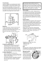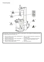
Remove the tyre
Remove any balance weights. Brush generously
with tyre mounting paste along with the entire
tyre bead. NOTE! Failure to lubricate the tyre bead
can cause serious damage to it. Place the wheel
centred on the table. To lock the rim to the table, do
this, depending on the diameter of the rim.
Rim diameter 10”–18”
Adjust the open position on the four clamping jaws
to hold the rim from the outside by depressing the
left foot pedal. Place the wheel on the clamping
jaws, and while pushing the rim down, press the
right foot pedal. Then check that the rim is securely
locked to the table using the four clamping jaws.
Rim diameter 12”–22”
Adjust the position of the four clamping jaws so
that they are completely closed. Place the wheel
on the four clamping jaws and press the left foot
pedal so that the clamping jaws open and then lock
the rim from the inside of the rim edge. Then check
that the rim is securely locked to the table using
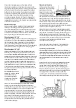
the four clamping jaws. Loosen the vertical arm
(M) using the lever (K) and lower it until the moun
-
ting head rests 2-3 mm from the rim and tyre side.
Then lock the vertical arm using the lever. Insert
the tyre iron between the tyre bead and the front of
the mounting head.
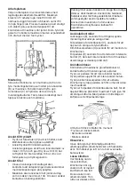
By depressing the foot
pedal (Z), the tyre bead
will be lifted above
the mounting head,
connecting the table
starting to rotate.
NOTE! To avoid damaging an inner hose (when
fitted), it is recommended to perform this step
starting from a point where the inner valve air valve
stem ends up approx. 2-3 cm to the right of the
mounting head. The tyre iron in place allows the
table to rotate clockwise by depressing the foot
pedal completely. Continue the procedure until the
tyre bead is completely removed from the rim.
Remove the inner tube (if fitted) and then repeat
the procedure of removing the tyre bead on the
other side of the tyre.
Move the tyre so that the tyre bead passes under
the front of the mounting head and lifts against the
edge of the rear of the mounting head. Using your
hands, press the tyre bead into the groove of the
rim. Then depress the foot pedal to rotate the table
clockwise. Then continue this procedure until the
tyre bead is pushed down along the entire
circumference of the tyre.
Insert the inner hose (if used). Then repeat the
procedure for the other side of the tyre/wheel.
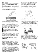
Mount on the tyre
At the same time check
that there are no foreign
particles on the tyre
bead, in the rim or the val
-
ve. Brush generously with
tyre fitting paste along
the tyre bead to avoid damage and facilitate the
fitting of the tyre. Lock the rim using the inside of
the clamping jaws. When working with rims of the
same size, it is not always necessary to raise/lower
the mounting head between the different jobs.
Instead, leave the mounting head locked in position
and move the swingarm sideways.
Auxiliary arm function
A pneumatic auxiliary arm for the tyre changer is
indispensable when fitting/dismounting low-profile
tyres and puncture-proof tyres and at times when
it is difficult to disassemble/mount an empty tyre,
then assistance from the auxiliary arm may be
required.
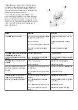
Drain the air from the tyre and release the clamp.
The rim can easily be damaged by the strong
forces that arise if you use the auxiliary arm,
therefore use protection on the clamping jaws.
Depress the foot pedal so that the clamping jaws
open and then lock the rim from the inside of the
rim edge. Press down the clincher with the
auxiliary arm to facilitate lubrication with tyre
mounting paste along with the entire tyre bead.
Place the clamping jaws on the table in their
innermost position so that they do not get in the
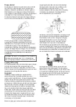
way. Open the clincher arm by moving it to the side
with your hand. Place the tyre against the rubber
buffer (S) on the machine, then align the clincher
so that the shoulder ends up about 10 mm from
the rim edge. Press the clincher pedal (U), the
arm then presses the tyre off the rim. Repeat for
another position on the tyre until it is completely
released from the rim. Turn the tyre over and do the
same for the other side.
Summary of Contents for 32836
Page 1: ...Tyre changer U 2011 D ckmaskin U 2011 Item No 32836...
Page 8: ...Varningsskyltarna...
Page 9: ......
Page 16: ...Exploded view...
Page 17: ......
Page 18: ......
Page 19: ......
Page 20: ......
Page 21: ......
Page 22: ......
Page 23: ......
Page 24: ......
Page 25: ...Electrical circuit diagram...
Page 26: ...Pneumatic diagram...
Page 28: ......
Page 29: ......


