background image

31

BOILER DIMENSIONS & RATINGS

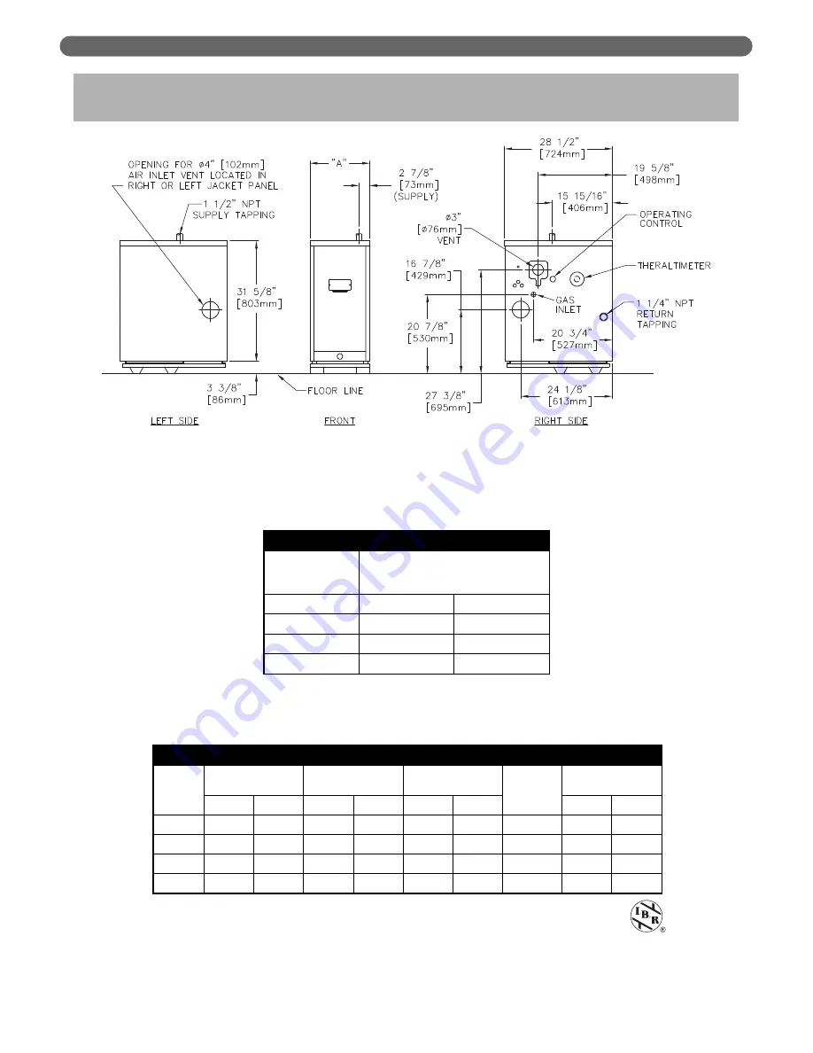
10. BOILER DIMENSIONS & RATINGS

Figure 10.1: Boiler Views

Table 10.1: Series PSC II™ Boiler Dimensions

Table 10.2: Series PSC II™ Boiler Ratings

1 Net I=B=R water ratings based on an allowance of 1.15.
2 Consult factory before selecting a boiler for installations having unusual piping and pickup

requirements, such as intermittent system operation, extensive piping systems, etc.

3 Heating Capacity and Annual Fuel Utilization Efficiency (AFUE) ratings are based on U.S.

Government test. 

SERIES PSC II™ BOILER DIMENSIONS

Boiler

Model

Number

Jacket Width “A”

PSCII-03

12-1/2"

318 mm

PSCII-04

15-7/8"

403 mm

PSCII-05

19-1/4"

489 mm

PSCII-06

22-5/8"

575 mm

SERIES PSC II™ BOILER RATINGS

Boiler
Model

Number

Input

DOE Heating

Capacity

3

Net I=B=R 

Ratings Water

1,2

Seasonal

Efficiency

3

(AFUE)%

Water Content

MBH

kW

MBH

kW

MBH

kW

Gallon

Liter

PSCII-03

65

19

56

16

49

14

86.0

4.72

17.87

PSCII-04

90

26

77

23

67

20

85.0

6.00

22.71

PSCII-05

120

35

102

30

89

26

85.0

7.28

27.56

PSCII-06

150

44

128

37

111

32

85.1

8.56

32.40

Summary of Contents for PSC II Series

Page 1: ...PSC II Boilers Series Gas Installation Operation Maintenance Manual As an ENERGY STAR Partner PB Heat LLC has determined that this product meets the ENERGY STAR guidelines for energy efficiency ...

Page 2: ...T PIPE INSTALLATION 12 G AIR FOR VENTILATION 12 H BOILER REMOVAL FROM COMMON VENTING SYSTEM 12 5 GAS PIPING 14 6 ELECTRICAL 15 A WIRING 15 B ZONED SYSTEM WIRING 15 C CONTROLS 15 D SEQUENCE OF OPERATION 16 7 START UP PROCEDURES 19 A COMPLETING THE INSTALLATION 19 B CONTROL DESCRIPTIONS 22 C ADJUSTMENT OF GAS PRESSURE REGULATOR 22 D CHECKING BURNER INPUT 22 E CHECK OUT PROCEDURE 22 8 TROUBLESHOOTING...

Page 3: ...supplement the instructions and make special notice of potential hazards These categories mean in the judgment of PB Heat LLC 1 USING THIS MANUAL Indicates special attention is needed but not directly related to potential personal injury or property damage NOTICE Indicates a condition or hazard which will or can cause minor personal injury or property damage CAUTION DANGER Indicates a condition or...

Page 4: ... Massachusetts code A hard wired carbon monoxide detector with an alarm and battery back up must be installed on the floor level where the gas equipment is to be installed AND on each additional level of the dwelling building or structure served by the side wall horizontal vented gas fueled equipment In the event that the side wall horizontally vented gas fueled equipment is installed in a crawl s...

Page 5: ...n a room or structure separate from the dwelling building or structure used in whole or in part for residential purposes This boiler installation manual shall remain with the boiler at the completion of the installation See the latest edition of Massachusetts Code 248 CMR for complete verbage and also for additional non vent related requirements 248 CMR is available online If your installation is ...

Page 6: ...ralized with respect to the heating system 2 Locate boiler in front of installation position before removing crate 4 Separate the wood shipping pallet from the boiler base by removing two 2 hold down bolts at each end of the boiler base 5 Move boiler into final position BOILER SET UP 2 BOILER SET UP ...

Page 7: ...e inlet connection of the circulator 3 Supply Piping a Pipe the supply to the 1 1 2 NPT supply tapping at the top of the boiler b Provide clearance to venting system see Section 4 4 When system return water temperature will be below 130 F 54 C pipe the boiler with a bypass arrangement to blend the system return and hot supply to obtain at least 130 F 54 C entering the boiler For more information o...

Page 8: ... the boiler water during the cooling cycle 9 If this boiler is installed above radiation level provide a low water cutoff device either as a part of the boiler or at the time of boiler installation B SAFETY RELIEF VALVE 1 Locate safety relief valve and fittings in bag assembly 2 If air elimination is not required at the safety relief valve tapping install valve and piping as shown in Figure 3 3 3 ...

Page 9: ...ystem layouts 2 Run each zone pipe down then up to zone to prevent air accumulation in piping 3 If required provide means to isolate and drain each zone separately 7 WATER PIPING AND CONTROLS Figure 3 5 Zone Piping with Zone Valves Figure 3 6 Zone Piping with Circulators ...

Page 10: ...ust be freeze protected 1 Glycol in hydronic applications is specially formulated for this purpose It includes inhibitors which prevent the glycol from attacking metallic system components Make certain that the system fluid is checked for the correct glycol concentration and inhibitor level 2 The glycol solution should be tested at least once a year and as recommended by the antifreeze manufacture...

Page 11: ...be 6 feet 2 meters h Do not locate vent terminal over public walkways where condensate could create a nuisance or hazard i When adjacent to a public walkway locate vent terminal at least 7 feet 2 1 meters above grade j Do not locate directly under roof overhangs to prevent icicles from forming 2 Cut a 5 1 8 130 mm square hole in sidewall to allow Peerless Wall Thimble to go through 3 Insert Thimbl...

Page 12: ...diameter collar on bottom of Thimble and secure hose clamp over collar and vent pipe as per step 7 above 11 Secure Inside Thimble cap to Wall Thimble with 10 screws Seal Thimble Cap perimeter with silicone 12 Seal all openings between Wall and Thimble and around the 3 76 mm diameter stainless steel vent pipe that protrudes through inside and outside of Wall Thimble 13 Add any bracing that may be n...

Page 13: ...E TRAP INSTALLATION Locate condensate hose and cable tie in Accessory Carton Connect hose to drain fitting on condensate elbow Form a 3 diameter loop and secure with cable tie Fill loop with water Pipe to drain or condensate receiver See Figure 4 2 VENTING VENTILATION AND AIR INLET Table 4 1 Table 4 2 Figure 4 3 Vertical Venting System Each 90 elbow equals 5 feet 1 5 meters of equivalent length Bo...

Page 14: ...ximum service temperatures Openings should be fixed in the open position during operation H BOILER REMOVAL FROM VENTING SYSTEM At the time of removal of an existing boiler follow these steps with each appliance remaining connected to the common venting system placed in operation while the other appliances remaining connected to the common venting system are not in operation a Seal any unused openi...

Page 15: ...ation is shown in Figure 5 1 7 Check piping for leaks prior to placing the boiler in operation Use an approved gas detector a non corrosive leak detection fluid or other leak detection method If leaks are found turn off all gas flow and repair as necessary 8 Disconnect the boiler and its individual shut off valve from the gas supply piping system during any pressure testing of that system at test ...

Page 16: ... 7 890 25 2 40 12 2 130 3 7 245 6 9 500 14 2 760 21 5 50 15 2 115 3 3 215 6 1 440 12 5 670 19 0 60 18 3 105 3 0 195 5 5 400 11 3 610 17 3 Boiler Model Natural Gas Input LP Gas Input Cu Ft hr Cu Meter hr Cu Ft hr Cu Meter hr PSCII 03 65 1 8 26 0 7 PSCII 04 90 2 5 36 1 0 PSCII 05 120 3 4 48 1 4 PSCII 06 150 4 2 60 1 7 Specific Gravity 0 50 0 55 0 60 0 65 0 70 0 75 Correction Factor 1 10 1 04 1 00 0 ...

Page 17: ...plied with safety devices in addition to the limit For a description of these devices and how they work to ensure the safe operation of the boiler see Section 7 4 If the circulator is mounted in the supply piping provide longer wiring harness as required ELECTRICAL 6 ELECTRICAL This unit when installed must be electrically grounded in accordance with the requirements of the authority having jurisd...

Page 18: ...R 1 and flame roll out switch 6 Gas valve energizes a Igniter on b Pilot gas on igniting pilot 7 Pilot flame detected a Igniter off b Main gas on igniting main burners Note If pilot flame is not detected within 30 seconds the igniter is turned off for 30 seconds and then turned back on for another 30 seconds If the pilot remains undetected in this second ignition period the igniter and pilot are t...

Page 19: ...17 ELECTRICAL Figure 6 3 Ignition System Operating Sequence ...

Page 20: ...18 ELECTRICAL Figure 6 4 Zone Wiring with Zone Valves Figure 6 5 Zone Wiring with Circulators ...

Page 21: ...lt the valve and expansion tank manufacturer for more specific information 7 Check joints and fittings throughout the system for leaks If leaks are found drain the system and repair as required 8 Connect a manometer to the 1 8 NPT inlet pressure tap on the gas valve See Figure 7 2 9 Confirm that the gas supply pressure to the boiler is above the minimum and below the maximum values for the gas bei...

Page 22: ...20 START UP PROCEDURES Figure 7 1 Gas Valve Manifold and Burner Assembly Intermittent Ignition Figure 7 2 Valve Tapping and Adjustment Screw Locations ...

Page 23: ...21 START UP PROCEDURES Figure 7 3 Operating Instructions ...

Page 24: ...nifold pressure vary more than 0 3 inches water column 0 07 kPa from the above specified pressures Any necessary major changes in the flow should be made by changing the size of the burner orifice spuds 4 When adjustment is complete turn off boiler gas flow and electricity to boiler Remove manometer and plug tapping with plug provided Turn utilities back on and resume checkout D CHECKING BURNER IN...

Page 25: ...l User s Information Manual and Vent Manufacturer s Information Manual in an accessible position near the boiler START UP PROCEDURES Table 7 1a Meter Conversion Natural Gas U S Customary Units Table 7 1b Meter Conversion Natural Gas SI Metric System Burner inputs in kW for various meter timings and heating values Tables based on 0 0566 cubic meters of gas through the meter Burner inputs in Btu hr ...

Page 26: ...m 0 45 W C 112 Pa fan suction pressure to energize control circuit Measure when boiler has been operating at least 15 minutes See Figure 8 1 TROUBLESHOOTING 8 TROUBLESHOOTING Should overheating occur or the gas supply fail to shut off do not turn off or disconnect the electrical supply to the pump This may aggravate the problem and increase the likelihood of boiler damage Instead shut off the gas ...

Page 27: ...layed ignition 1 Insufficient pilot flame 2 Pilot burner orifice clogged 3 Overfiring 4 Misaligned burners or pilot 1 Increase pilot gas flow 2 Clean pilot burner and orifice 3 Reduce rate to input on rating label 4 Realign burners or pilot Boiler not heating properly 1 Underfiring 2 Limit set too low 3 Air in system 4 Circulator malfunctioning 5 Circulation system clogged 6 Incorrect thermostat h...

Page 28: ...WITH IGNITER POWERED SEE INSET A TO IDENTIFY PROPER LEAD THIS CHECK MUST BE DONE WITH THE GAS VALVE CONNECTED AND IGNITER POWERED TURN ON GAS SUPPLY PILOT BURNER LIGHTS CHECK THAT PILOT FLAME MAKES GOOD CONTACT WITH PILOT BURNER FLAME ROD CHECK FOR GOOD ELECTRICAL CONNECTION THROUGH THE PILOT TUBING IF BOTH OF THE ABOVE ARE GOOD REPLACE IGNITER FLAME ROD ASSEMBLY NO NO 1 CHECK FOR 24VAC AT PRESSUR...

Page 29: ...rovide adequate ventilation Wear a NIOSH MSHA approved respirator Wear long sleeved loose fitting clothing and gloves to prevent skin contact Wear eye goggles Minimize airborne dust prior to handling and removal by water misting the material and avoiding unnecessary disturbance of materials Wash work clothes separately from others Rinse washer thoroughly after use Discard RCF materials by sealing ...

Page 30: ... 250 F 121 C 4 Check for water leaks in boiler and system piping 5 Smell around the appliance area for gas If you smell gas follow the procedure listed in the Operating Instructions to shut down appliance in Figure 7 3 C WEEKLY WITH BOILER IN USE 1 Flush float type low water cut off if used to remove sediment from the float bowl as stated in the manufacturer s instructions D MONTHLY WITH BOILER IN...

Page 31: ... pilot burners hitch pin clips Reconnect pilot harness to gas valve gently pulling harness to length required to reach gas valve q Reinstall air box diffuser r Examine air box cover seal Reposition replace as necessary to assure air tight seal s Reinstall air box cover t Examine entire vent system for corrosion support and joint integrity Repair as necessary Remove any debris inside vent u Reconne...

Page 32: ...30 MAINTENANCE Figure 9 2 Inspection of Flueways Burners and Vent System ...

Page 33: ... Capacity and Annual Fuel Utilization Efficiency AFUE ratings are based on U S Government test SERIES PSC II BOILER DIMENSIONS Boiler Model Number Jacket Width A PSCII 03 12 1 2 318 mm PSCII 04 15 7 8 403 mm PSCII 05 19 1 4 489 mm PSCII 06 22 5 8 575 mm SERIES PSC II BOILER RATINGS Boiler Model Number Input DOE Heating Capacity3 Net I B R Ratings Water1 2 Seasonal Efficiency3 AFUE Water Content MB...

Page 34: ...ts are available from your installer or by contacting PB Heat LLC New Berlinville PA Use the figures and tables on pages 32 36 to assist in ordering parts Note Remember to include boiler model number and serial number when ordering parts 11 REPAIR PARTS Figure 11 1 ...

Page 35: ...r Screen PSCII 04 PSC2025 1 Air Box Diffuser Screen PSCII 05 PSC2025 2 Air Box Diffuser Screen PSCII 06 PSC2025 3 10 Rope Gasket Seal Air Box 50718 11 Flame Rollout Switch Thermodisc G4AM00_167C 51587 12 Flame Rollout Switch Bracket 50136 13 Steel Burner PSCII 03 3 51536 Steel Burner PSCII 04 5 51536 Steel Burner PSCII 05 7 51536 Steel Burner PSCII 06 9 51536 Burner with Pilot Bracket 51535 14 Ori...

Page 36: ...34 REPAIR PARTS Figure 11 2 ...

Page 37: ...as Models Only PSCII 04 PSC5003 1 Orifice Plate Normal Altitude LP Gas Models Only PSCII 05 PSC5003 2 Orifice Plate Normal Altitude LP Gas Models Only PSCII 06 PSC5003 3 23 Fan 50775 24 Fan Adapter 50200 25 Jacket PSCII 03 90729 Jacket PSCII 04 90730 Jacket PSCII 05 90731 Jacket PSCII 06 90732 Gas Valve SV9501M2700 Natural Gas Models Only 51682 Gas Valve SV9501M2064 LP Gas Models Only 51691 Pilot ...

Page 38: ...36 NOTES ...

Page 39: ...37 NOTES ...

Page 40: ... is the property of the owner and must be affixed near the boiler for future reference TO THE OWNER This boiler should be inspected annually by a Qualified Service Agency PSC8055 R4 1 12 7 5C Printed in U S A 2012 PB Heat LLC All rights reserved ASME PB HEAT LLC 131 S CHURCH STREET BALLY PA 19503 ...

Reviews: