


called Sealtrode. Your installation may be furnished
with any of these according to original purchase
specifications.
FLOAT CONTROL:
The float control (when furnished)
is a type of liquid level control which provides
automatic operation of the pump unit.
On liquid level rise the float raises the float rod with
its fixed buttons until the lower button trips the float
switch, starting the pump. As the liquid level drops,
the upper float button trips the switch to the off
position, stopping the pump.
INSTALLING AND REGUATING THE STANDARD
FLOAT CONTROL:
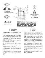
Locate the float mechanism
where provided for on the basin cover. The usual
float switch equipment consists of a float rod, float,
guide pipe for float rod, switch stand assembly and
float rod adjusting buttons. The specific arrangement
for the C84A fixed float system or the C93A sliding
float system must be taken from the instructions
furnished with your float control.
When adjusting the setting of the
low water cut-out level for any liquid
level control be sure that the liquid surface at pump
cut-out is above the top of the motor [see figure 1].
The motor is designed to operate submerged and
relies upon the liquid in which it is submerged to act
as its coolant. The temperature of the liquid being
pumped is not to exceed 105dF [40dC] to insure
proper cooling of the motor.
PUMP ALTERATION FOR DUPLEX UNITS:
When
the pumping unit consists of two pumps in a
common basin it is desirable to provide automatic
alternation of the pumps to insure equal wear and
allow
for
extra
heavy
periodic
flow
handling
capability.
Alternating control provides alternate operation of the
two pumping units on successive cycles as long as a
single pump can handle the pump load. However,
under peak flow conditions, when the liquid level
continues to rise more rapidly than can be handled
by one pump, both units are automatically placed in
operation.
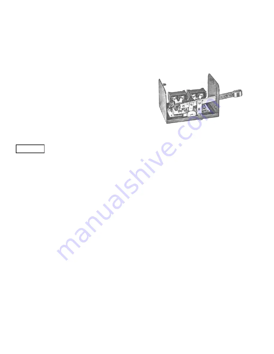
ALTERNATING TYPE FLOAT SWITCH:
The alternating
type float switch consists of two 2 pole float switches in
a single enclosure. The float switches are mechanically
connected through linkage which causes
MOTOR LUBRICATION:
No motor bearing lubrication
necessary. Motor bearings are sealed for life of unit.
alternate operation of the two pumping units. The
switch is controlled by the float which actuates the
switch on rise and fall of the liquid level. The action
is such that the two switches are alternated on
successive cycles. If the liquid level continues to rise
with one pump in operation, the switch lever arm will
continue to travel upward to a further position will
continue to travel upward to a further position at
which point the “second” switch will
operate,
starting the standby pump. The switch is illustrated
in figure 2.
Figure 2. Alternating Switch
CONTROLS:
It is recommended that a suitable
overload protector, or an across-the-line magnetic
starter be installed in the motor circuit to prevent
motor burn-outs if for some reason an overload
should occur. A float switch must not be used as the
primary starting device in 3-phase installations. It is
always used to pilot a magnetic starter. Some
1-phase installations also must employ the float
switch as a pilot device only. Check the horsepower
and voltage limit of the switch nameplate before
wiring to decide its proper use in a 1-phase circuit.
CAUTION
FUSES:
It is recommended that Fusetron (dual
element) fuses be used if not other thermal or motor
protecting device is used. The Fusetron provides for
motor protection against burn-out. Care must be
taken in selecting the proper size Fusetron. When a
fuse blows it indicates that something is wrong,
either in the motor, pump, switch, fuse rating or
service. Do not replace a fuse until you find and
remove the cause of the blow-out.
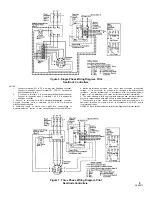
WIRING IMPORTANT:
Connect the electric service
to the controls and make inter control electrical
connections when necessary according to wiring
instructions accompanying the switches and motor,
using conduit and wire sizes as required by local
codes. Typical wiring diagrams are illustrated in
figures 4 thru 7. Be sure the current characteristics
of voltage and frequency indicated on motor
nameplates are the same as those of the service
provided.
LUBRICATION
PUMP LUBRICATION, FLOAT ROD SEAL:
Before
starting pump and at weekly intervals thereafter,
saturate the felt washer with SAE 30 oil.
5
2899213