background image

18

ISSUED: 2012-10-11    SHEET #: 180-9041-2   2012-05-31
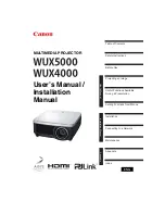
AMPLIFIER

GAIN

AUX

MIC

IR IN

AUDIO-REMOTE

Amplifi er

Main POWER Button (Unit)

Turns ON/OFF the unit’s main power.  If the main power button on the unit is not turned on the unit 
will not respond to remote control.  

Note: If the power is turned OFF using the face button while the unit is in stand-by mode, and then 
turned back on via the push button, the unit will remain in stand-by mode till the remote is used to 
turn it on.  

POWER Button

 (Remote Control) – The power button on the remote control allows toggling 

between STAND-BY mode and power ON mode. In the STAND-BY mode the unit is not fully turned 
off (the main push button turns the unit off completely and should only be pressed to turn ON the 
unit during installation).

Indicator Light

Off – When the indicator light is not active the unit is OFF
Red – When the indicator light is red the unit is in STAND-BY mode. (Main Power Button (On Unit) 
must be in the ON position)
Green – When the indicator light is green the unit is turned ON. (Main Power Button (On Unit) must 
be in the ON position)

AUDIO INPUTS

Two stereo audio inputs include Auxiliary and Microphone connections. When using the 
microphone (not included)  it is recommended to use a mono to stereo adapter (not included). 

VOLUME ADJUSTMENT 

(Unit and Remote Control)

Volume adjustment button on the unit or the remote control adjusts volume for the Auxiliary and 
Microphone input simultaneously. The indicator light for volume adjustment will 

fl

 ash during volume 

adjustment. 

MODE SWITCH

The MODE Switch toggles between the units Stereo and Mono mode.  When using the optional 
Microphone capability with this unit it is recommended to use the MONO mode for best audio 
results.

MIC GAIN ADJUSTMENT

The gain adjustment knob on the back of the unit goes from 0 (off) up to +10dB (at signal level) 
over the Auxiliary input.  

Summary of Contents for WL-AU-AVWS

Page 1: ...31 2300 White Oak Circle Aurora Il 60502 800 865 2112 Fax 800 359 6500 www peerless av com Installation and Assembly PeerSound Wireless AV Wall System PeerSound Wireless Audio Wall System Models WL AU AVWS WL AU AVWS W WL AU AVWSA WL AU AVWSA W ...

Page 2: ......

Page 3: ...ct should only be installed by someone of good mechanical aptitude has experience with basic building construction and fully understands these instructions Make sure that the supporting surface will safely support the combined load of the equipment and all attached hardware and components Never exceed the Maximum UL Load Capacity See page one If mounting to wood joists ceilings make sure that moun...

Page 4: ...80 1173 180 2173 G mic bracket 1 180 1189 180 2189 180 1189 180 2189 H cover assembly 1 180 1200 180 2200 180 1200 180 2200 I m5 x 6mm security screw 8 520 1114 520 2062 520 1114 520 2062 J cable bushing 2 590 1295 590 2295 590 1295 590 2295 K finishing cap 2 590 1123 590 2123 590 1123 590 2123 L cable tie anchor 3 600 0101 600 0101 600 0101 600 0101 M cable tie 3 560 9711 560 9711 560 9711 560 97...

Page 5: ...005 180 1005 EE vga to rca adapter for hds 200 1 180 1006 180 1006 FF remote controller for hds 200 1 180 1007 180 1007 GG battery cr2025 3v 1 180 0008 180 0008 HH ir flasher 1 180 1009 180 1009 II ir extender gen 2 1 180 0029 180 0029 JJ amplifier 25x2 2 input 1 180 1085 180 1085 180 1085 180 1085 KK amp kit 50w ac to dc power adapter 24v 2a 1 180 1088 180 1088 180 1088 180 1088 LL amp kit 50w ir...

Page 6: ...safely support the combined load of the equipment and all attached hardware and components Tighten wood screws so that wall plate is firmly attached but do not overtighten Overtightening can damage the screws greatly reducing their holding power Never tighten in excess of 80 in lb 9 N M Make sure that mounting screws are anchored into the center of the stud The use of an edge to edge stud finder i...

Page 7: ...e keyholes in the back of enclosure assembly A place enclosure assembly A on to the two screws C Slide enclosure assembly A over until the mark on the wall plate lines up with the center of the screw C as shown in detail A NOTE When mounting on 16 stud centers use bottom set of slots For 20 and 24 stud centers use top set of slots 1 KEYHOLE fig 2 2 fig 2 3 DETAIL A C 1 ...

Page 8: ...or thicker and metal stud must be 24 gauge or heavier Installer must verify that the supporting surface will safely support the combined load of the equipment and all attached hardware and components Not Evaluated By UL WARNING Product must be mounted through drywall that has a minimum thickness of 1 2 and into metal studs 24 gauge or heavier Make sure that togglers are anchored into the center of...

Page 9: ...e assembly A over until the mark on the wall plate lines up with the center of the 1 4 20 x 2 5 phillips screws P as shown in detail B NOTE When mounting on 16 stud centers use bottom set of slots For 20 and 24 stud centers use top set of slots 1 KEYHOLE fig 2 6 fig 2 7 DETAIL B P 1 Position enclosure on wall Install remaining two 1 4 20 x 2 5 phillips screws P Level enclosure assembly A and tight...

Page 10: ...of the hole when entering a void or cavity Concrete must be 2000 psi density minimum Lighter density concrete may not hold concrete anchor Make sure that the supporting surface will safely support the combined load of the equipment and all attached hardware and components Tighten screws so that wall plate is firmly attached but do not overtighten Overtightening can damage screws greatly reducing t...

Page 11: ...closure assembly A over until the mark on the wall plate lines up with the center of the screw C as shown in detail C NOTE When mounting on 16 stud centers use bottom set of slots For 20 and 24 stud centers use top set of slots 1 Position enclosure on wall Install remaining 2 screws C Level enclosure assembly A and tighten all screws fig 2 10 fig 2 9 C KEYHOLE DETAIL C ...

Page 12: ...e top or bottom of enclosure A Push the power cord through the bottom of the cable bushing J Push cable bushing J into hole in the enclosure A Plug into power source If your power source is located inside the enclosure push finishing cap K into top and bottom holes in the enclosure A D A J K A A Install power strip D onto mounting screws inside of enclosure assembly A 2 3 ...

Page 13: ...own Install HDS200 receiver assembly into enclosure A using two M5 x 6mm screws Q Install amp brackets F into enclosure A using two M5 x 6mm screws Q Q E BB A F A Q 4 5 Continue to step 4 for WL AU PST600 W WL AU PST1200 W WL AU PST1600 W Models Skip to step 5 for WL AU PST600A W WL AU PST1200A W WL AU PST1600A W Models ...

Page 14: ...D 2012 10 11 SHEET 180 9041 2 2012 05 31 Install amp JJ between amp brackets F and secure using two M4 x 10mm screws R as shown R F JJ OPTIONAL Install wireless mic receiver not included into area provided 6 7 ...

Page 15: ...and two M5 x 6mm screws Q 8 Install IR extenders to bottom of enclosure assembly A as shown NOTE Place double sided tape included with IR extender LL to bottom of IR extender first then install to bottom of enclosure assembly A as shown 9 DOUBLE SIDED TAPE NOTE IR extender II is used on WL AU AVWS W models only ...

Page 16: ...16 ISSUED 2012 10 11 SHEET 180 9041 2 2012 05 31 Route connector ends of IR extenders through holes in bottom of enclosure assembly A as shown 10 A ...

Page 17: ... OUT HDMI OUT Component Connections II H BB CC LL JJ KK NN SPEAKERS PRE WIRED TO MIC RECEIVER NOT INCLUDED SEE NEXT PAGE Use the following diagram to make the component connections NOTE For transmitter setup instructions refer to the Installation and Operation section of the HDS200 user manual WL AU AVWS W models only 11 ...

Page 18: ...ve the unit is OFF Red When the indicator light is red the unit is in STAND BY mode Main Power Button On Unit must be in the ON position Green When the indicator light is green the unit is turned ON Main Power Button On Unit must be in the ON position AUDIO INPUTS Two stereo audio inputs include Auxiliary and Microphone connections When using the microphone not included it is recommended to use a ...

Page 19: ...em is installed the relative gain to the HDS200 needs to be set For fixed level sources Blu Ray player 1 Play source with amplifier volume at a comfortable level 2 Adjust mic gain the the back of the amplifier while talking into the microphone to allow vocals to be slightly louder than the fixed source volume 3 Confirm no feedback or mic hotness is present at high amplifier volumes 4 Fine tune as ...

Page 20: ...ese Seite wurde absichtlich freigelassen Deze pagina is met opzet blanco gelaten Pagina lasciata intenzionalmente vuota Tato strana je záměrně prázdná Táto strana je zámerne prázdna Esta página foi intencionalmente deixada em branco Bu sayfa özellikle boş bırakılmıştır ENG ESP FRN DEU NEL ITL ČEŠ SLK POR TÜR ...

Page 21: ...rvice or repairs by Peerless AV b the failure to utilize proper packing when returning the product c incorrect installation or the failure to follow Peerless AV s instructions or warnings when installing using or storing the product or d misuse or accident in transit or otherwise including in cases of third party actions and force majeure This warranty also does not cover corrosion or rust resulti...

Page 22: ...ese Seite wurde absichtlich freigelassen Deze pagina is met opzet blanco gelaten Pagina lasciata intenzionalmente vuota Tato strana je záměrně prázdná Táto strana je zámerne prázdna Esta página foi intencionalmente deixada em branco Bu sayfa özellikle boş bırakılmıştır ENG ESP FRN DEU NEL ITL ČEŠ SLK POR TÜR ...

Page 23: ...ese Seite wurde absichtlich freigelassen Deze pagina is met opzet blanco gelaten Pagina lasciata intenzionalmente vuota Tato strana je záměrně prázdná Táto strana je zámerne prázdna Esta página foi intencionalmente deixada em branco Bu sayfa özellikle boş bırakılmıştır ENG ESP FRN DEU NEL ITL ČEŠ SLK POR TÜR ...

Page 24: ...Peerless AV 2300 White Oak Circle Aurora IL 60502 Email tech peerlessmounts com Ph 800 865 2112 Fax 800 359 6500 www peerless av com 2012 Peerless Industries Inc ...

Reviews: