


-22
-12
-30
-22
-12
-30
-18
OFF
ON
PROCESS
-15
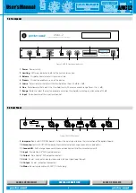
AMCL-2
Controller & Limiter
Automatic Multiband
-15
.15
-4
.25
dB
INPUT
0
-2
.2
-8
-10
-6
.4
4
6.5
sec
RELEASE
7
2.5
1
1.3
1.5
-3
LIMITING (dB)
-9
-12
-6
0
POWER
User’s Manual
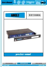
AMCL2
SOUND REINFORCEMENT
ACOUSTIC RESEARCH
CONTROLLED RADIATION
6
7. FEATURE DESCRIPTION
The Peecker Sound Automatic Multiband Controller & Limiter (AMCL2)
is a multiband device expressly designed to control the sound
pressure level (SPL) within a space. It belongs to the category of
devices commonly called
dynamic processors
capable of acting on
the audio signal level or width in a variable way, depending on the
spectral distribution of the audio signal itself. Dynamic processors
are designed to optimize the signal based on the features of the
transmitting device being used or the type of appliances adopted for
the sound reproduction system.
When talking about the
dynamic range
of a music program, we mean
the
difference
, normally expressed in dB, between
the maximum
(undistorted)
level reached by the signal and its minimum “useful” level
,
i.e. capable of being perceived by the human ear. The maximum output
signal of an appliance is normally limited by the adjustment of the
power supply side, since the excursion can never exceed the supply
voltage. Minimum output level, on the other hand, is determined by
the background noise level, since a signal whose level is below that of
background noise cannot actually be picked up. Modern professional
equipment can produce a dynamic range capable of reaching up to as
much as 120 dB.
Multi-band limiters are used to reduce the dynamics of the input
signals being received. This reduction is determined by the fact that a
highly dynamic signal is difficult for a sound reinforcement system to
handle, which is indeed the reason why existing regulations impose
limits on audio signal levels.
Typically, such devices are used for amplification systems in public
venues where sound pressure equivalent level (Leq) and maximum
level (Lmax) cannot exceed the limits required by the applicable
national rules and regulations. Using a suitably configured AMCL2 unit
allows the system to comply with such restrictions even if the source
signal has been unintentionally adjusted to exceed them.
Unlike traditional systems, the AMCL2 guarantees the highest quality
result, where the sound is free from modulations or unpleasant
“pumping” effects that may lead to volume fluctuations. Thanks to the
possibility to manage different frequency bands
(Low, Mid and High
),
the musical message is optimized for the entire frequency range,
producing rich and modulated bass notes and crystal clear high notes.
7.1 Advantages of multi-band limiters over wideband ones
The use of multi-band limiters has become necessary in the world
of professional audio to make up for the shortcomings of wideband
limiters, which suffer from the problem of spectral intermodulation
distortion where, in practice, the linear combination of incoming
signals causes a spectral alteration of the overall gain, thereby
producing intermodulation effects. Typical examples of this problem
include situations in which the voice signal drops as a result of a drum
roll, for example, or when an extra, unplanned speaker is introduced,
causing a reduction in the overall spectral content.
Low frequencies – which have a higher energy content – normally tend
to control the entire spectral content; when the lowest frequencies
exceed a set threshold limit, the high frequencies are attenuated and
consequently the sound output becomes dull and restrained.
Unlike wideband limiters, multiband limiters do not behave this way
but actually produce a spectral separation of the audio signal into
multiple frequency bands so that they can be processed separately.
This can lead to more serious design and implementation problems,
but these can be resolved by using an “intelligent circuit” capable of
controlling all the parameters automatically, thereby keeping to a
minimum the set of controls.
6. CONNECTIONS
Check that your mains power voltage corresponds to that
indicated on the back of the unit.
Before connecting the cable to the AC mains make sure it is
undamaged and that there are no bare cables.
Remember to turn off the limiter before connecting it to or disconnecting it
from any other units.
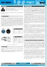
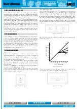
6.1 Connection cables
Input and output wiring diagrams are shown in Figure 4.
Neutrik® XLR
connectors are used for connecting the main audio inputs and outputs,
while 6.3 mm
stereo Jacks
are used for auxiliary connections. To guarantee the
maximum performance, both inputs and outputs are balanced without the
use of transformers. In any case, the cross-coupled output stage allows for
both balanced and unbalanced connection without noticeable differences in
level. In the case of unbalanced connection, the unused pin (2 or 3) must be
short-circuited with pin 1 (GROUND), and in this case, the 70 Ω impedance
of the outputs allows you to drive even long capacitive lines without any
problems. Finally, the jumper on the rear panel allows you to select NORMAL
or CAL operation when tuning the system.
XLR BAL INPUT/OUTPUT
Pin 1
GND
Pin 2
HOT+
Pin 3
COLD-
JACK INPUT/OUTPUT
Pin 1 (Sleeve)
GND
Pin 2 (Ring)
COLD-
Pin 3 (Tip)
HOT+
Pin 4
Insulating
rings
Figure 4. Cannon® XLR and Jack connectors
6.2 Power supply
The appliance is designed to operate with a 230 VAC – 50/60Hz mains power
supply.
Should the unit fail to work when switched on, check the protection fuse; if
it blows immediately, do not try to resolve the matter yourself but have the
appliance checked by a qualified service centre.


