background image

12

PUMP BELT ADJUSTMENT

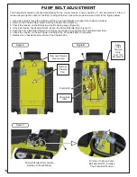
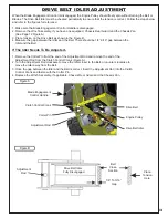
The Pump Belt should be checked periodically for the correct tension. There should be 1” of movement for 10 lbs. of 
tension applied to the center of the Belt. To adjust the Belt, follow the steps below and refer to the figures below:

1. Use a floor jack to raise the machine off the ground and blocks to support the chassis and deck.
2. Remove the Chassis Rear Guard and the Chassis Pan (Figure A). 
3. Check the tension on the Belt using a belt tension gauge (Figure B). 
4. If the belt tension needs adjustment, loosen the Pump Belt Idler Bolt (Figure C).  
5. Push the Pump Belt Idler forward to increase the tension, then tighten the Pump Belt Idler Bolt.
6. Check the tension on the belt again, and adjust the Pump Belt Idler if necessary.
7. Replace the Chassis Rear Guard and the Chassis Pan.

Remove Chassis

Rear Guard

Remove

Chassis

Pan

Pump Belt

Pump Belt

Idler

Apply

10 lbs.

Tension

Here

For 1” Of

Movement

Pump Belt Idler Bolt Location

Relative To Brush Blazer

Direction To Move Pump

Belt Idler Bolt To Increase

The Pump Belt Tension

Figure A

Figure C

Figure B

Summary of Contents for BRUSH BLAZER TBB-3002

Page 1: ...B 3002 MODEL TBB 3002 MODEL TBB 3002 by BRUSH BRUSH BRUSH BRUSH BRUSH BLAZER BLAZER BLAZER BLAZER BLAZER R R R P P P PECO PECO PECO PECO PECO PECO P P P P P P P P PECO PECO R R R OPERATOR S MANUAL OPE...

Page 2: ...d to call attention to safety precautions that Should be followed by the operator to avoid accidents When you see this symbol carefully read the message that follows and heed its advice Failure to com...

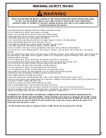
Page 3: ...essively steep Keep children and pets out of the operating area and under close adult supervision Stop the machine immediately if children or pets enter the work area Never allow children to operate t...

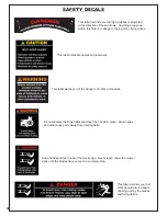
Page 4: ...es This label warns you of the dangers of carbon monoxide Do not operate the Brush Blazer without the hoods in place Keep hands and other body parts away from rotating belts Keep hands and feet clear...

Page 5: ...rate manufacturer warranties and those companies must be contacted directly to file a warranty claim Briggs Stratton https www briggsandstratton com na en_us support warranty html 2 UNAPPROVED ALTERAT...

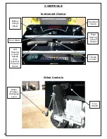
Page 6: ...CONTROLS Blade Engage Disengage Lever Other Controls Battery Charge Meter Hour Meter Left Steering Control Handle With Operator Presence Switch Key Start Switch Right Steering Control Handle Throttle...

Page 7: ...with the controls and descriptions in the section below Starting The Brush Blazer 1 Place Your Left Hand On The Left Steering Control Handle 2 Push The Throttle Control Forward 3 Turn The Key Switch...

Page 8: ...the Steering Control Handles back towards you at the same time Pull back slightly to move slowly in reverse Pull back harder to increase the speed of your reverse movement Reverse Movement Keep your...

Page 9: ...ndle Grab the Left Steering Control Handle with your left hand and push forward to steer right Push the control forward slightly to steer slowly Pushing the control harder will execute a sharper turn...

Page 10: ...iately Try moving in reverse and backing away from the obstacle Cutting Brush And Saplings The Brush Blazer can cut saplings up to 4 in diameter When cutting saplings or brush allow the Brush Blazer t...

Page 11: ...To The Right If the machine pulls to the right when traveling forward adjust the Right FRS Rod by first loosening the Adjustment Locking Nut Figure A Next turn the Right FRS Rod counter clockwise one...

Page 12: ...on the Belt using a belt tension gauge Figure B 4 If the belt tension needs adjustment loosen the Pump Belt Idler Bolt Figure C 5 Push the Pump Belt Idler forward to increase the tension then tighten...

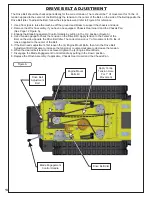
Page 13: ...gap between the Idler and the Belt If The Idler Needs To Be Adjusted 1 Remove the Cotter Pin from the end of the Adjustment Rod and remove the end of the Adjustment Rod from the Clutch Control Crank...

Page 14: ...position Figure A 4 Use a tension gauge to check the tension on the Drive Belt Apply tension to the center of the Belt on the side opposite the Drive Belt Idler The correct tension is 1 of movement f...

Page 15: ...tension 5 When proper tension is achieved tighten the Deck Adjustment Flange Nuts 6 Tighten the Deck Mounting Bolts MOWER DECK PULLEY ALIGNMENT 1 Use a plumbers level on the Counter Shaft Pulley 2 Us...

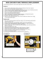
Page 16: ...s on the Counter Shaft Figure H Replacement 1 Wrap one end of the Drive Belt around the lower Pulley on the Counter Shaft and feed the Belt towards the Engine Pulley 2 Wrap the Deck Belt Pulley around...

Page 17: ...Hardware Remove Belt From Pulley Pivot The Counter Shaft Forward Remove Adjustment Bolts Loosen Deck Mounting Bolts Remove Deck Belt Remove Drive Belt DECK AND DRIVE BELT REMOVAL REPLACEMENT Figure C...

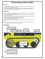
Page 18: ...ly loosened you can then push the Complete Front Axle towards the rear of the Brush Blazer 3 Place the Track onto the Rear Sprocket first and align the Sprocket teeth to the center of the Track allowi...

Page 19: ...or damage Warped bent severely broken or chipped Blades should be replaced Sharpening Before sharpening determine if the Blade s width falls between the dimensions in Figure B If the Blade width is le...

Page 20: ...P P P P PECO PECO PECO PECO Inc Innovative Outdoor Power Equipment 100 Airport Road Arden NC 28704 Phone 800 438 5823 Fax 828 684 0858 e mail peco lawnvac com DECK DECK DECK 48 P P P PECO PECO PECO P...

Page 21: ...emove the deck and engine hood 2 Remove the Donaldson air filter cover 3 Remove the air filter from the housing 4 Replace the air filter 5 Replace the Donaldson air filter cover 6 Replace the deck and...

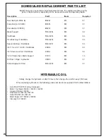
Page 22: ...10 x 2 1 4 SHCS Flail Blade K0298 300 06 3 4 Stover Lock Nut Flail Blade K0302 300 04 1 2 20 Nyloc Nut Blade Support K1018 600 10 Oil Filter Zinga Hydraulics U0030 050 01 Kohler Engine Oil Filter TBB...

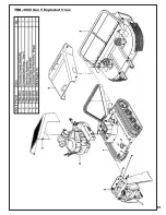
Page 23: ...23 TBB 3002 Gen 5 Exploded View...

Page 24: ...24 TBB 0671 Complete Chassis Assembly Exploded View...

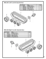
Page 25: ...25 TBB 0651 Left Track Kit Exploded View TBB 0652 Right Track Kit Exploded View...

Page 26: ...26 TBB 0657 C Shaft Drive Kit Exploded View...

Page 27: ...27 TBB 0665 Hydraulic Drive Kit Exploded View...

Page 28: ...28 TBB 0628 Complete Deck Assembly Exploded View...

Page 29: ...29 TBB 0620 Blade Shaft Flange Hub Kit Exploded View...

Page 30: ...30 TBB 0629 Blade Kit Single Shaft Exploded View TBB 0606 Blade Shaft Sheave Kit Exploded View...

Page 31: ...31 TBB 0600 Deck Hood Assembly Exploded View...

Page 32: ...32 TBB 0601 Chassis Hood Assembly Exploded View...

Page 33: ...33 TBB 0601 Chassis Hood Assembly Exploded View...

Page 34: ...34 TBB 0675 Right FRS Kit Exploded View...

Page 35: ...35 TBB 0676 Left FRS Kit Exploded View...

Page 36: ...36 TBB 0672 Hydro Tank Kit Exploded View TBB 0680 Dash Kit Briggs Stratton Exploded View...

Page 37: ...37 TBB 0674 Dash Assembly Exploded View...

Page 38: ...38 TBB 0687 Briggs Stratton 36HP Vanguard Engine Kit Exploded View...

Page 39: ...39...

Page 40: ...ur brush cutter or part has failed due to abuse neglect or improper maintenance or unapproved modifications You are responsible for presenting your Brush Blazer to New PECO Inc s distribution center o...

Page 41: ...arranty period stated above New PECO Inc will maintain a supply warranted parts sufficient to meet the expected demand of such parts 7 Any replacement part may be used in performance of any warranty m...

Page 42: ...10 Walden Dr Arden North Carolina 28704 Phone 1 800 438 5823 828 684 1234 Fax 828 684 0858 Email info brushblazer com Website www brushblazer com P P P PECO PECO PECO PECO PECO PECO P P P P P P P P P...

Reviews: