


14
29
19
2
3
1
21
18
35
10
4
17
23
15
34
30
6
16
26
39
25
5
11
20
28
24
12
13
33
7
9
40
8
27
38
32
31
37
36
22
44
45
9
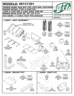
Exploded Parts View
Exploded View Of The
A0610 - PTO Assembly
Item
Number
Document
Number
Title
Quantity
1
A0593
PTO ARM ASSY.
1
2
A0429
GEAR BOX ASSEMBLY
1
3
A0436
BELT TENSION BRACKET
ASSEMBLY
1
4
B0076
BELT GUIDE BRACKET
1
5
K0348
3/8"-16 x 2" ALL THREAD
HHCS
1
6
K0047
3/8" FLAT WASHER 1.00 OD x
.446 ID x .075 T
1
7
K1193
3/8"-16 x 1-1/2" HHCS
6
8
K1215
3/8"-16 FLANGE NUT
8
9
K1197
3/8"-16 X 2 1/2" HHCS
1
10
B0075
PULLEY GUARD
1
11
K0353
1/4"-20 x 1/2" HHSTS
4
12
K1159
5/16"-18 x 2" ALL THREAD
HHCS
1
13
K1178
5/16"-18 FLANGE NUT
5
14
A0144
BLOWER MOUNT BRACKET
ASSEMBLY
1
15
B1755
BLOWER PIVOT ROD
1
Item
Number
Document
Number
Title
Quantity
16
K0086
.125 OD x 2.50 HAIR PIN CLIP
2
17
B0121
BLOWER BELT GUARD
1
18
A0604
PTO HANDLE MOUNT ASSY
1
19
A0422
CAM BRACKET ASSEMBLY
1
20
K0356
3/8"-16 TAPERED SET
SCREW
1
21
A0603
PTO HANDLE ASSEMBLY
1
22
V1151
5/8" ID x 4-3/4" BLACK
HANDLE GRIP
1
23
B0162
SKID PLATE
1
24
K1142
5/16"-18 x 3/4" CARRIAGE
BOLT
4
25
K0326
BELT TENSION ROD 3/8"-16
1
26
K0130
.091 OD x 1.625 L HAIR PIN
CLIP
1
27
K1222
1/4"-20 X 3/4" HHCS
3
28
K1128
1/4"-20 NYLOC NUT
3
29
A0306
PTO SHAFT ASSEMBLY
1
30
J0254
3/16" SQ. x 3/4" LONG
KEYWAY
1
Item
Number
Document
Number
Title
Quantity
31
M0228
BLOWER PULLEY
1
32
K1446
1.187 OD x .380 ID x .187
WASHER
1
33
K1190
3/8"-16 x 3/4" HHCS
1
34
E4004A
BLOWER HSG. ASSY.
1
35
A0645
SMALL 4-BLADE IMPELLER
1
36
S4302
TAPER-LOCK BUSHING
1
37
S3242
PLATED BUSHING
1
38
K1225
1/4"-20 X 1" HHCS GRADE 8
2
39
K0278
TAPER-LOCK BUSHING
WASHER
1
40
K1211
3/8"-16 x 1-1/2" HHCS GRADE
8
1
41*
E6009
8" BLOWER CONE
1
42*
K0125
5/16"-18 x 2-1/2" ALL THREAD
HHCS
2
43*
K0120
5/16"-18 JAM NUT
2
44
M0237
A33K
1
45
M0247
A53K
1
KEVLAR BELT
FOR 31HP
KAWASAKI
A52K
M0238
FOR ALL
OTHER ENGINES
/ M0238


