Peco 48131301 Operator'S Manual Download Page 7

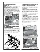
2-7 Mount Tube Stiffener and Debris 

Shield Installation

Place the lower mount tube stiffener P#(B0247) between 
the lower mount tube and the rear guard as shown in 
Figure 2-7. Align the holes in the debris shield 
P#(B0624) with the holes in the rear guard and secure 
both parts to the rear guard with (2) 1/2”-13 x 1” HHCS 
P#(K1231), (2) ½” flat washer P#(K0055), and (2) 1/2”-
13 nyloc nut P#(K1247). Fasten the lower mount tube 
P#(B0246) to the lower mount tube stiffener, using (1) 
3/8”-16 u-bolt P#(K1432) and (2) 3/8”-16 nyloc nuts 
P#(K1216). Refer to Figures 2-7a and 2-7b.  

7

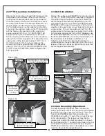
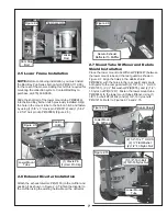
2-5 Lower Frame Installation

NOTE:

 Before continuing installation, you must install 

the Bad Boy Pup Series bolt-on hitch P#(093-1112-00) 
for the rear of the mower. Adding this hitch is required for 
mounting the collection system. Contact Bad Boy to 
purchase at (870) 698-0090.

Slide the short leg of the lower mount tube P#(B0246) 
into the Bad Boy bolt-on hitch previously installed. Align 
the hole in the mount tube to the bolt-on hitch and fasten 
by using (1) 5/8” x 3” clevis pin P#(K0172) and (1) 5/32” 
x 2-5/8” hair pin clip P#(K0088) (Figure 2-5).
 

2-6 Exhaust Diverter Installation

Attach the exhaust diverter P#(J0150) to the muffler and 
position it as shown in Figure 2-6. Tighten the diverter to 
the muffler using the existing hardware on the deflector.  

Figure 2-4

Cam Assembly

Cam Stop

Bolt

Tension

Rod

Figure 2-5

Lower Mount

Tube

Bad Boy

Hitch

(1) Clevis Pin

(1) Hair Pin Clip

Secure Exhaust 

Deflector To Muffler

Figure 2-6

Figure 2-7a

Figure 2-7b

(2) 1/2”-13 x 1” HHCS

(2) ½” Flat Washer

(2) 1/2”-13 Nyloc Nut 

Lower Mount

Tube Stiffener

Debris Shield

Lower Mount

Tube

(1) 3/8”-16 U-Bolt

(2) 3/8”-16 Nyloc Nut

Summary of Contents for 48131301

Page 1: ...OPERATOR S MANUAL PTO GRASS COLLECTION SYSTEM DESIGNED FOR ASSEMBLY OPERATION MAINTENANCE MODEL 48131301 PUP OUTLAW LIGHTNING SERIES MOWERS MANUAL PART Q0336 4 00 REV 0...

Page 2: ...shut off deck and attachment set parking brake shut off mower engine and remove spark plug wire before removing clogs or removing or replacing hose boot blower cone or performing any maintenance 9 Mo...

Page 3: ...LVED This symbol is used to call attention to safety precautions that should be followed by the operator to avoid accidents When you see this symbol carefully read the message that follows and heed it...

Page 4: ...teries and gearboxes attached to PECO products are covered under a separate warranty by the respective manufacturer D UNAPPROVED ALTERATION OR MODIFICATION All obligations of PECO Inc under this warra...

Page 5: ...parts The collection system will have various parts located inside Remove and sort all parts for easy identification NOTE Before each step of assembly it will help to study the exploded drawings on p...

Page 6: ...ar box is moved towards the mower s engine pulley Connect the kevlar cord belt from the engine pulley to the lower gear box pulley Figure 2 3b For all engine sizes except for the 31HP Kawasaki use the...

Page 7: ...g this hitch is required for mounting the collection system Contact Bad Boy to purchase at 870 698 0090 Slide the short leg of the lower mount tube P B0246 into the Bad Boy bolt on hitch previously in...

Page 8: ...2 6 J4009 SHORT RUBBER STRAP W S HOOK 2 7 K0037 1 4 FLAT WASHER 75 OD x 314 ID x 060 T 2 8 K1128 1 4 20 NYLOC NUT 2 9 C0026 GRASS DEFLECTOR 1 10 K0062 3 16 x 1 1 2 FENDER WASHER Z 4 11 K1265 BLACK PA...

Page 9: ...T GUARD 1 18 A0604 PTO HANDLE MOUNT ASSY 1 19 A0422 CAM BRACKET ASSEMBLY 1 20 K0356 3 8 16 TAPERED SET SCREW 1 21 A0603 PTO HANDLE ASSEMBLY 1 22 V1151 5 8 ID x 4 3 4 BLACK HANDLE GRIP 1 23 B0162 SKID...

Page 10: ...10...

Page 11: ...ollowing photo for clarity Always have the deflector shield mounted when mowing 2 8 Upper Frame Assembly Installation NOTE During this step it is suggested that two people install the upper frame to t...

Page 12: ...ach bolt evenly into the taper lock bushing forcing the blade to break away from the taper lock bushing If the impeller will not move carefully hit the base of the impeller between each vein with a ha...

Page 13: ...ion Slide a 8 hose clamp P J0080 over both ends of the lower hose Then proceed to slide the lower hose onto the blower cone Tighten the hose clamp The assembly should look like Figure 2 13 2 16 Lower...

Page 14: ...d Figure 2 18b To empty the bag remove the bag and bag ring by lifting and sliding rearward Grasp the loop on the bottom of the bag turn it upside down and empty the collected debris Figure 2 18c Repe...

Page 15: ...ss is extra tall Remember that horsepower requirements will vary with the mowing conditions such as type and height of turf grass moisture content amount of leaves whether the terrain is flat or hilly...

Page 16: ...ation NOTE Use only white lithium based grease for lubrication of the shaft on the blower assembly 1 On initial use Grease the fitting on the blower shaft 2 Every 25 hours of use Re grease the grease...

Page 17: ...ty decals on all products manufactured Damage can occur to safety decals either through shipment use or reconditioning Contact your local Service Center for replacement decals Part R1050 Part R1054 Pa...

Page 18: ...18 Bad Boy...

Page 19: ...NOTES 19...

Page 20: ...With your Bad Boy Wand Attachment you will double the ability of your Bad Boy Lawn Vac Using the same powerful vacuum blower that makes your Lawn Vac work so well you will be able to get to all those...

Reviews: