


7
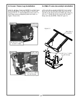
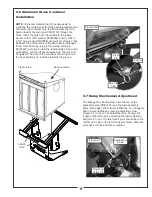
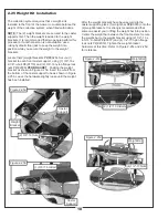
2-3 Lower Frame Leg Installation
Attach the left lower frame leg P#(B0725) and right lower
frame leg P#(B0724) to the rear bumper of the mower
using (4) 3/8”-16 x 1” HHCS P#(K1191) and (4) 3/8”-16
nylon flange locknuts P#(K2038) PER LEG. Refer to
Figure 2-3a and 2-3b.
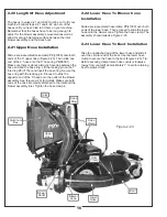
2-4 Main Frame Assembly Installation
Lift the main frame assembly P#(A1833) into position
above the left and right lower frame legs. Secure the
main frame assembly to the lower frame legs using (4)
3/8”-16 x 1” HHCS P#(K1191) and (4) 3/8”-16 nylon
flange locknuts p#(K2038). Refer to Figure 2-4.
Figure 2-3b
Figure 2-3a
Left Lower
Frame Leg
Right Lower
Frame Leg
(4) 3/8”-16 x 1” HHCS
(4) 3/8”-16 Nuts
(4) 3/8”-16 x 1” HHCS
(4) 3/8”-16 Nuts
Figure 2-4
Main Frame
Assembly
(4) 3/8”-16 x 1” HHCS
(4) 3/8”-16 Nuts
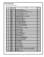
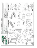
Summary of Contents for 37721231
Page 22: ...22 A0664 Boot Kit ...
Page 23: ...23 B1117 A0664 Boot Kit ...
Page 24: ...24 B1117 A0664 Boot Kit ...
Page 28: ...28 ...
Page 29: ...NOTES ...


