Peco 37721231 Operator'S Manual Download Page 4

4

PECO LIMITED WARRANTY FOR NEW PRODUCTS

A. WHAT IS UNDER WARRANTY?
 

PECO extends the following warranties to the original purchaser of each new PECO consumer product subject 


to the following limitations.

1. PRODUCT WARRANTY: 

Any part of any consumer product, which is defective in material or workmanship as


delivered to the purchaser will be repaired or replaced, as PECO elects, without charge for parts or labor, if the


defect appears within 12 months (On most products, see owners manual for specifics) from the date of delivery  

of the product to the original purchaser.

 ALL DEFECTIVE PARTS MUST BE RETURNED TO PECO 


FOR INSPECTION TO DETERMINE VALIDITY OF WARRANTY CLAIMS. 

Freight and mailing will 


be borne by the customer.

2. PARTS REPLACED DURING WARRANTY: 

Any new PECO part which is furnished in performance of this


warranty and is defective in material or workmanship as delivered to the purchaser will be repaired or replaced,  

as PECO elects, without charge if the defect appears within 90 days from the date of installation of such part or
 

before the expiration of the original warranty period, whichever is later.

B. SECURING WARRANTY ADJUSTMENTS.
 

Call PECO for Return Authorization. Damaged or broken parts other than engines or batteries, must be


returned to New PECO Inc., 100 Airport Road, Arden, NC 28704 before any warranty adjustment can be 


authorized. At the time of requesting warranty adjustment, the purchaser must present evidence of the date of 


delivery of the product. The purchaser shall pay any charge for the product to and from Arden, NC.

C. ITEMS NOT COVERED BY PECO WARRANTY.
 

Engines and batteries attached to PECO products are covered under a separate  warranty by the respective


manufacturer.

D. UNAPPROVED ALTERATION OR MODIFICATION.
 

All obligations of New PECO, Inc. under this warranty shall be terminated if products are altered or modified in 


ways not approved by New PECO Inc.

E. ACCIDENTS AND NORMAL MAINTENANCE.
 

The warranty covers only defective material and workmanship. It does not cover depreciation or damage


caused by normal wear, accident, improper use or abuse of products. The cost of normal maintenance and


normal replacement of service items such as belts, cutting blades, hoses, etc., which are not defective shall be


paid for by the purchaser.

F. NO REPRESENTATIONS ADDITIONAL WARRANTIES, DISCLAIMER.
 

Neither New PECO Inc. nor any company affiliated with it makes any warranties, representations or promises 


as to the quality of performance of its products other than those set forth herein. Except as described above, 


New PECO Inc. makes no other warranties 

AND SPECIFICALLY DISCLAIMS ANY AND ALL 


IMPLIED WARRANTIES OF FITNESS AND MERCHANTABILITY.

G. ANY MACHINE USED FOR RENTAL PURPOSES ARE GUARANTEED FOR 45 DAYS FROM DATE


OF ORIGINAL SALE ONLY.

H. REMEDIED EXCLUSIVE.
 

The only remedies the purchaser has in connection with the breach or performance of any warranty on New 


PECO Inc. consumer products are set forth above. In no event will PECO be liable for special incidental or


consequential damages.

1. NO SERVICE CENTER WARRANTY.
 

The selling Service Center makes no warranty on his own on any item warranted by New PECO Inc. unless he


delivers to purchaser a separate written warranty certificate specifically warranting the item. The dealer has no


authority to make any representation or promise on behalf of PECO or to modify the terms of this warranty in


any way.

Summary of Contents for 37721231

Page 1: ...RASS COLLECTION SYSTEM OPERATOR S MANUAL MODEL 37721231 PTO DRIVE MODEL 37721232 900 SERIES BRIGGS STRATTON MODEL 37721233 6 5HP BRIGGS STRATTON VANGUARD 52 61 VELOCITY PLUS DECK 2012 MODEL YEAR TIGER CAT P PECO PECO P P P P PECO PECO PECO DESIGNED TO FIT ...

Page 2: ...Wear eye protection to prevent debris from damaging your eyes SECTION PAGE Safety 2 Safety Alert Symbols 3 Warranty 4 I INTRODUCTION AND DESCRIPTION 5 1 1 Introduction 5 1 2 Description 5 II INSTALLATION FOR USE 5 2 1 Preparation Of Mower 6 2 2 Lower Mount Plate Installation 6 2 3 Lower Frame Leg Installation 7 2 4 Main Frame Assembly Installation 7 2 5 Lift handle Installation 8 2 6 Aluminum Gras...

Page 3: ...OLVED This symbol is used to call attention to safety precautions that Should be followed by the operator to avoid accidents When you see this symbol carefully read the message that follows and heed its advice Failure to comply with safety precautions could result in death or serious bodily injury Safety Signs The signal words DANGER WARNING and CAUTION are used on the equipment safety signs These...

Page 4: ...nes and batteries attached to PECO products are covered under a separate warranty by the respective manufacturer D UNAPPROVED ALTERATION OR MODIFICATION All obligations of New PECO Inc under this warranty shall be terminated if products are altered or modified in ways not approved by New PECO Inc E ACCIDENTS AND NORMAL MAINTENANCE The warranty covers only defective material and workmanship It does...

Page 5: ...grass clippings as the mower cuts the turf It is also used for picking up leaves and in pre season and post season clean up The blower mounted on the right side of the unit uses a belt and gearbox system from the engine PTO shaft Drive train protection comes through belt slippage The blower is also available with an external engine option of 5 5HP or 6 5HP The blower draws grass clippings from the...

Page 6: ...y P K1628 and the flat washer removed in Section 2 1b Refer to Figure 2 1c for reference On units with the Donaldson air cleaner loosen the hardware and rotate the air cleaner to the forward most position See Figure 2 1d 2 2 Lower Mount Plate Installation Attach the lower mount plate P B0719 to the rear of the mower Use the existing hardware removed in Section 2 1 The lower mount plate attaches to...

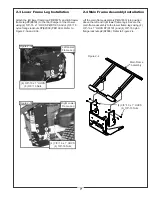
Page 7: ...Frame Assembly Installation Lift the main frame assembly P A1833 into position above the left and right lower frame legs Secure the main frame assembly to the lower frame legs using 4 3 8 16 x 1 HHCS P K1191 and 4 3 8 16 nylon flange locknuts p K2038 Refer to Figure 2 4 Figure 2 3b Figure 2 3a Left Lower Frame Leg Right Lower Frame Leg 4 3 8 16 x 1 HHCS 4 3 8 16 Nuts 4 3 8 16 x 1 HHCS 4 3 8 16 Nut...

Page 8: ...n in Figure 2 5d using 1 5 16 24 hex nut P K1444 and 1 5 16 lock washer P K0043 Attach the other end of the latch rod to the lift handle as shown in Figure 2 5e Attach on end of the spring P J0176 to the lift handle and the other end of the spring to the handle mount bracket as shown in Figure 2 5f Adjust the ball joint up or down on the latch rod threads until the latch hook closes completely Aft...

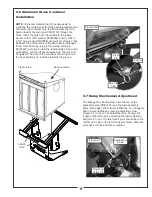
Page 9: ...pull the lift handle away from the unit and lift upward The door of the container should open and the box should pivot clockwise towards the ground 2 7 Dump Mechanism Adjustment The linkage may be adjusted in two places at the adjusting screw P K1435 and the latch assembly items See page 10 for visual clarification To change the door closure tightness screw the adjusting screw Figure 2 7 in or out...

Page 10: ... NUT B0193 LINKAGE ROD J0176 LATCH SPRING J0522 HANDLE GRIP A0574 BOX HANDLE V1152 INLET RING W LOCKING PIN B8113 SCREEN B0205 BASE FRAME B1529 LATCH HOOK B0192 BASE FRAME PIVOT MOUNT K1442 ADJUSTING BALL JOINT A0557 DOOR FRAME ASSEMBLY C0031 BOX BACK SIDES B1730 HANDLE MOUNT A0558 BOX DOOR FRAME V1131 PLASTIC DOOR B0194 UPPER DOOR MEMBER B1574 PIVOT BRACKET A0087 LATCH HOOK PIVOT PLATE ...

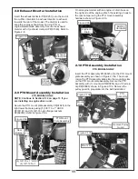
Page 11: ...all engine models with an engine oil drain hose on the right side of the engine attach the existing J hook to the rear bumper using the PTO mount assembly hardware shown in Figure 2 9b 2 10 PTO Assembly Installation PTO MODELS ONLY Insert the PTO assembly P A0623 into the PTO mount plate assembly as shown in Figure 2 10a The mount rod on the PTO assembly slides into the mounting slots on the PTO m...

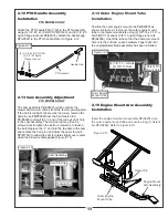
Page 12: ...rn the adjustment bolt clockwise Figure 2 11e until there is 1 of deflection with 10 11 lbs of pressure at the center of the belt between the engine pulley and the gear box pulley Once the correct tension of the belt is achieved tighten the 4 bolts that secure the gear box assembly Refer to Figures 2 11f and 2 11g Replace the belt guard and hardware that was removed in Section 2 10 Loosen Bolts Fi...

Page 13: ...allow the cam to rotate slightly over center when the blower is disengaged Figure 2 13 2 14 Outer Engine Mount Tube Installation Position the outer engine mount tube P B2220 as shown in Figure 2 14 Secure the outer engine mount tube to the lower mount plate using 2 3 8 16 x 2 18 u bolt P K1119 and 4 3 8 16 nylon flange lock nuts P K2038 Orient the tube so that the detent pin mount hole is to the o...

Page 14: ... the boot plate P B0309 on top of the aluminum boot P E0012 as shown in Figure 2 18a Secure the boot plate to the boot using 2 3 8 16 x 1 carriage bolts P K1182 and 2 3 8 16 nylon flange lock nuts P K2038 Insert the bolts from the inside of the boot so that the threads are on the outside of the boot This will prevent any grass clippings from collecting on the threads To attach the boot to the mowe...

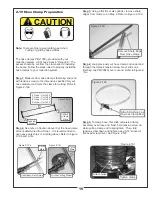
Page 15: ... Figure 2 19b and 2 19c Step 3 Using a flat file or disc grinder remove sharp edges from clamp cut in Step 2 Refer to Figure 2 19d Step 4 Loop previously cut hose clamp end under and through the clamp s tension screw Next slide one finishing cap P V0040 over cut end Refer to Figure 2 19 e Step 5 To clamp hose first slide completed clamp assembly over hose end Next hold tension screw up while pulli...

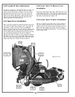
Page 16: ... with the locking pin Proceed to slide the opposite end of the 6 hose onto the outlet of the blower assembly See Figure 2 23 for details Make sure both ends of the hose are clearly attached to the inlet and the blower assembly inlet Tighten the hose clamps 2 22 Lower Hose To Blower Cone Installation Slide a pre assembled hose clamp P J1000 over both ends of the lower hose Then proceed to slide the...

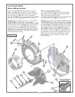
Page 17: ...to the specifications located in the chart towards the back of this manual Last rotate the impeller blade to ensure that the blade is clear of contact on all sides of the blower housing 2 24 Impeller Blade Removal Replacement To gain impeller blade 1 access first remove the blower cone 2 from the blower housing located on the PTO assembly P A1821 by removing two blower cone bolts and nuts 3 Next r...

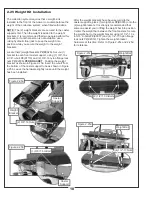
Page 18: ...8 PER BRACKET Position the weight bracket as shown in Figure 2 25a Insert the u bolt from the bottom of the caster support tube as shown in Figure 2 25b Leave the hardware slightly loose until the weight has been installed After the weight brackets have been secured to the caster supports place 1 weight bar P B0035 onto the 2 weight brackets It is strongly recommended that someone assist you in li...

Page 19: ...le to the blower housing assembly using 1 J Clip P K1455 Use the existing hardware from the blower housing to secure the J Clip as shown in Figure 2 26c To fasten the throttle cable end to the engine place the throttle control lever into the stop position Rotate the engine throttle lever to the stop position Thread the wire end of the throttle cable into the engine throttle lever eyelet and tighte...

Page 20: ...ISO VIEW 7 12 1 11 31 32 23 10 29 30 8 39 36 20 16 40 3 9 15 27 14 2 4 13 5 6 19 33 21 34 28 22 26 18 17 37 38 25 24 Exploded Parts View A0623 PTO Assembly 20 M0241 A50K BELT INCLUDED IN H W BAG ...

Page 21: ...4 3 16 SQ x 3 4 LONG KEYWAY 1 17 M0228 BLOWER PULLEY 1 18 K1446 1 187 OD x 380 ID x 187 WASHER 1 19 K1190 3 8 16 x 3 4 HHCS 1 20 E4004A BLOWER HSG ASSY 1 21 K1193 3 8 16 x 1 1 2 HHCS 4 22 K1215 3 8 16 FLANGE NUT 12 23 A0645 SMALL 4 BLADE IMPELLER 1 24 S4302 TAPER LOCK BUSHING 1 25 S3242 PLATED BUSHING 1 26 K1225 1 4 20 X 1 HHCS GRADE 8 2 27 K0278 TAPER LOCK BUSHING WASHER 1 28 K1211 3 8 16 x 1 1 2...

Page 22: ...22 A0664 Boot Kit ...

Page 23: ...23 B1117 A0664 Boot Kit ...

Page 24: ...24 B1117 A0664 Boot Kit ...

Page 25: ...t of leaves whether the terrain is flat or hilly etc 3 3 Disengagement Of The Blower PTO MODELS A To disengage the blower rotate the engagement handle towards the mower WARNING The blower will continue to spin DO NOT TOUCH the blower pulleys or the belt until the tractor is turned off DO NOT adjust the belt tension until the mower is turned off Refer to section of the manual 2 10 ENGINE DRIVEN MOD...

Page 26: ... Lubrication For PTO Models NOTE Use only white lithium based grease for lubrication of the shaft on the blower assembly 1 On initial use Grease the fitting on the blower shaft 2 Every 25 hours of use Re grease the grease fitting 3 Every 200 hours of use Check oil levels in gear box Oil in gear box should cover the gears If necessary fill using an EP90 weight oil 6oz will fill the gear box from em...

Page 27: ...n occur to safety decals either through shipment use or reconditioning Contact your local Service Center for replacement decals Part R1054 Part R1052 Part R1049 Part R1057 Part R1053 Part R1055 Part R1051 27 Part R4037 Part R1070 Part R1065 Part R1083 Part R4027 Part R1069 Part R4008 Part R4015 R2008 R2007 ...

Page 28: ...28 ...

Page 29: ...NOTES ...

Page 30: ...100 AIRPORT ROAD ARDEN NORTH CAROLINA 28704 800 438 5823 OR 828 684 1234 FAX 828 684 0858 EMAIL peco lawnvac com WEBSITE www lawnvac com P PECO PECO P P P P PECO PECO PECO ...

Reviews: