background image

SECTION III

OPERATING 

INSTRUCTIONS

3-1  General Safety

Only qualified people familiar with this operator’s manual 
and the mower’s operator’s manual should operate this 
machine.

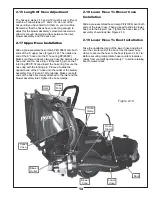
3-2  Operation & Tips On Mowing

A. Perform BEFORE EACH USE maintenance list in 
     paragraph 4-1.
B. Start the engine/blower/blade assembly.
B. Start mower.
C. With the mower at high idle speed, engage the mower 
     deck.
D. Proceed to operate the control levers of the mower.

Note:

 If the collection system does not appear to be 

collecting the grass clippings; disengage the deck,
and blower, engage the parking brake and turn the 
mower off. Check the upper hose, lower hose, top 
screen and boot for clogs.

To obtain the maximum effectiveness from your 
collection system the tips listed below should be 
followed:

* Watch your speed- Normal conditions will allow a 
   speed of up to approximately 5 mph, but thick, heavy 
   damp conditions will require reduced ground speed.
* Mow with sharp blades- A sharp blade cuts cleaner.
* Wet grass and leaves will decrease effectiveness and 
   will increase horsepower requirements.
* Mow at higher cutting heights- Remove and mulch no 
   more than 2” of grass length with each mowing. 
  (Experts recommend not cutting off more than 1/3 of 
   the grass blade length at any given time.)
* Mow twice, at different height settings, (high, then low),
   if grass is extra tall.
* Remember that horsepower requirements will vary with 
   the mowing conditions such as type and height of turf
   grass, moisture content, amount of leaves, whether the 
   terrain is flat or sloped, etc.

3-3  Unloading The Collection System

Note: 

 Press the tab, located behind the operator’s left 

side, downward to feel if the collection system is full. If 
the container is full there will be resistance when 
depressing the tab.

21

A. Stop the forward movement of the mower.
B. Disengage the mower deck.
C. Using the throttle cable slow the engine down to idle.
D. Push the dump handle, on the left of the operator, 
     away from the unit. While holding the handle pushed 
     away, move the handle upward. The container door 
     will swing upward and the container will rotate 
     downward. The container will release its contents.
E. Once the contents of the container have fallen out, 
     the container is ready to move back into its normal 
     operating position. With the handle in the ‘away’ 
     position, pull the handle downward until it stops. 
     Move the handle towards the center of the mower. 
     This motion will allow the latch to lock back into 
     collection position.

Note:

 If you do not hold the handle away from the 

mower as you pull the handle downward, the latch will 
not lock and the container can unexpectedly release the 
contents collected.
 

SECTION IV

MAINTENANCE

4-1 Maintenance Checklist

Before each use:
1. Check blades and spindles to be sure that no foreign 
     objects, such as wire or steel strapping bands, are 
     wrapped around them.
2. Inspect blades for wear. Replace if necessary. If it is 
     necessary to sharpen the blades, remove the blades 
     from the spindles before sharpening. DO NOT 
     sharpen blades while still attached to the mower.
3. Make sure all shields are in place and in good 
     condition. Repair or replace any missing or damaged 
     shields.
4. Listen for abnormal sounds, which might indicate 
     loose parts, damaged bearings, or other damage.
     Correct any deficiency before continuing operation.
5. Check for wear or deterioration of the upper or lower 
     hoses. If there are any portions of the hose that have 
     been torn or worn through, replace with genuine 
     PECO parts.

After Each Use:

1. Clean all debris from machine especially from the 
     container, and off of safety decals. Replace any 
     missing or illegible decals.
2. Clean all debris from the box screen.
3. Inspect unit for worn or damaged components. Repair 
     or replace before the next use. Any replacement 
     component installed during repair shall include the 
     components current safety decal specified by the 
     manufacturers to be affixed to the component.

Summary of Contents for 05721201

Page 1: ...ENANCE MANUAL PART Q0461 PTO GRASS COLLECTION SYSTEM OPERATOR S MANUAL MODEL 05721202 900 SERIES BRIGGS STRATTON MODEL 05721201 6 5HP BRIGGS STRATTON VANGUARD P PECO PECO P P P P PECO PECO PECO DESIGNED TO FIT S150XT 2012 2013 ...

Page 2: ...y foreign object 12 Wear ear protection if the noise level is offensive 13 Wear eye protection to prevent debris from damaging your eyes SECTION PAGE Safety 2 Safety Alert Symbols 3 Warranty 4 I INTRODUCTION AND DESCRIPTION 5 1 1 Introduction 5 1 2 Description 5 II INSTALLATION FOR USE 5 2 1 Preparation Of Mower 5 2 2 Left and Right Frame Bracket Installation 6 2 3 Rear Frame Bracket Installation ...

Page 3: ...OLVED This symbol is used to call attention to safety precautions that Should be followed by the operator to avoid accidents When you see this symbol carefully read the message that follows and heed its advice Failure to comply with safety precautions could result in death or serious bodily injury Safety Signs The signal words DANGER WARNING and CAUTION are used on the equipment safety signs These...

Page 4: ... to PECO products are covered under a separate warranty by the respective manufacturer D UNAPPROVED ALTERATION OR MODIFICATION All obligations of New PECO Inc under this warranty shall be terminated if products are altered or modified in ways not approved by New PECO Inc E ACCIDENTS AND NORMAL MAINTENANCE The warranty covers only defective material and workmanship It does not cover depreciation or...

Page 5: ...f It is also used for picking up leaves and in pre season and post season clean up The engine blower blade assembly is mounted on the right side of the mower The blower draws grass clippings from the discharge area of the cutter deck back to the 12 cubic foot aluminum box at the rear portion of the mower frame The operator can engage the blower on the right side of the unit by starting the externa...

Page 6: ... B0801 and right frame bracket P B0802 to the rear frame of the mower where the rear bumper was removed Use the existing hardware from the rear bumper as shown in Figure 2 2 6 Figure 2 2 Existing Hardware Left Frame Bracket Right Frame Bracket Existing Hardware Existing Hardware ...

Page 7: ...S P K1222 and 1 1 4 20 nylon flange locknut P K2014 PER BRACKET Leave the hardware finger tight Secure both muffler guard brackets to the existing muffler guard using 1 1 4 20 x 3 4 HHCS P K1222 and 1 1 4 20 nylon flange locknut P K2014 PER BRACKET Tighten all hardware at this time Refer to Figure 2 4 Figure 2 4 2 3 8 16 x 1 Hex Bolts 2 3 8 16 Locknuts Rear Frame Bracket Right Frame Bracket Left F...

Page 8: ...eave the hardware finger tight until the engine blower blade assembly has been installed Refer to Figure 2 6 2 6 Engine Mount Arm Assembly Installation Insert the engine mount arm assembly P A0274 into the outer engine mount tube and secure with 1 detent pin P J0248 Refer to Figure 2 6 Figure 2 6 2 3 8 16 x 3 U Bolts Outer Engine Mount Tube Engine Mount Arm Assembly Detent Pin 4 3 8 16 Locknuts ...

Page 9: ... and 4 5 16 18 nylon flange lock nuts P K2516 as shown in Figure 2 7b Adjust the position of the outer engine mount tube so that the blower housing has at least 1 of clearance from the rear tire Tighten the u bolts on the outer engine mount tube at this time Figure 2 7a Figure 2 7b 4 5 16 18 x 1 1 2 Hex Bolts 4 5 16 18 Locknuts Outer Engine Mount Tube Engine Blower Blade Assembly Engine Mount Arm ...

Page 10: ...igure 2 8a and 2 8b 2 9 Main Frame Assembly Installation Lift the main frame assembly P A0596 into position and secure to the left and right frame legs using 4 3 8 16 x 1 HHCS P K1191 and 4 3 8 16 nylon flange locknuts P K2038 Refer to Figure 2 9 Figure 2 9 Main Frame Assembly 4 3 8 16 x 1 Hex Bolts 4 3 8 16 Locknuts Figure 2 8a Figure 2 8b 2 1 2 13 x 1 Hex Bolts 2 1 2 13 Locknuts Left Frame Brack...

Page 11: ...in Figure 2 10d using 1 5 16 24 hex nut P K1444 and 1 5 16 lock washer P K0043 Attach the other end of the latch rod to the lift handle as shown in Figure 2 10e Attach on end of the spring P J0176 to the lift handle and the other end of the spring to the handle mount bracket as shown in Figure 2 10f Adjust the ball joint up or down on the latch rod threads until the latch hook closes completely Af...

Page 12: ...p mechanism pull the lift handle away from the unit and lift upward The door of the container should open and the box should pivot clockwise towards the ground 2 12 Dump Mechanism Adjustment The linkage may be adjusted in two places at the adjusting screw P K1435 and the latch assembly items See page 20 for visual clarification To change the door closure tightness screw the adjusting screw Figure ...

Page 13: ...grass deflector on the discharge chute Insert 1 boot rod P B0348 through the outside set of mounting holes on the deflector bracket as shown in Figure 2 15a Secure the bot rod with 1 hair pin clip P K0099 Install the aluminum boot P E1902 with the top inside surface of the boot flush to the top surface of the mower deck Secure the aluminum boot to the boot plate using 2 3 8 16 x 1 carriage bolts P...

Page 14: ...e ring with the locking pin Proceed to slide the opposite end of the 6 hose onto the outlet of the blower assembly See Figure 2 19 for details Make sure both ends of the hose are clearly attached to the inlet and the blower assembly inlet Tighten the hose clamps 2 18 Lower Hose To Blower Cone Installation Slide a pre assembled hose clamp P J1000 over both ends of the lower hose Then proceed to sli...

Page 15: ...to the specifications located in the chart towards the back of this manual Last rotate the impeller blade to ensure that the blade is clear of contact on all sides of the blower housing 2 20 Impeller Blade Removal Replacement To gain impeller blade 1 access first remove the blower cone 2 from the blower housing located on the PTO assembly P A1821 by removing two blower cone bolts and nuts 3 Next r...

Page 16: ... weight into position while you secure the weight to the weight bracket Attach the weight bracket P B0523 to the front frame of the mower using the existing holes Secure the weight bracket using 2 1 2 13 x 1 HHCS P K1231 and 2 1 2 13 nylon flange locknuts P K2012 Refer to Figure 2 21a Position 1 weight bar P B2220 on top of the weight bracket as shown in Figure 2 21b Center the weight bar on the w...

Page 17: ... Throttle Base Plate Throttle Spring Plate Throttle 2 22 Throttle Cable Installation To install the throttle cable kit P A0060 to the box assembly align the large end of the slot in the throttle base plate Figure 2 22a with the rivets located on the front of the box assembly frame Figure 2 22b Place the throttle base plate over the rivets Slide the throttle cable kit to the right moving the smalle...

Page 18: ... NUT B0193 LINKAGE ROD J0176 LATCH SPRING J0522 HANDLE GRIP A0574 BOX HANDLE V1152 INLET RING W LOCKING PIN B8113 SCREEN B0205 BASE FRAME B1529 LATCH HOOK B0192 BASE FRAME PIVOT MOUNT K1442 ADJUSTING BALL JOINT A0557 DOOR FRAME ASSEMBLY C0031 BOX BACK SIDES B1730 HANDLE MOUNT A0558 BOX DOOR FRAME V1131 PLASTIC DOOR B0194 UPPER DOOR MEMBER B1574 PIVOT BRACKET A0087 LATCH HOOK PIVOT PLATE ...

Page 19: ...19 ...

Page 20: ...20 ...

Page 21: ...able slow the engine down to idle D Push the dump handle on the left of the operator away from the unit While holding the handle pushed away move the handle upward The container door will swing upward and the container will rotate downward The container will release its contents E Once the contents of the container have fallen out the container is ready to move back into its normal operating posit...

Page 22: ...s unable to service your collection system or supply replacement parts contact PECO and include the following information on the chart below THE SERIAL NUMBER PLATE IS LOCATED ON THE BOX ASSEMBLY P A0560 Unit Model Number _____________________________ Unit Engine Size _____________________________ Unit Serial Number _____________________________ Date of purchase _____ _____ _________ Dealer Distri...

Page 23: ...age can occur to safety decals either through shipment use or reconditioning Contact your local Service Center for replacement decals Part R1054 Part R1052 Part R1049 Part R1057 Part R1053 Part R1055 Part R1051 23 Part R4037 Part R1070 Part R1065 Part R4027 Part R1069 Part R4008 Part R4015 R2008 R2007 ...

Page 24: ...24 ...

Page 25: ...10 WALDEN DRIVE ARDEN NORTH CAROLINA 28704 800 438 5823 OR 828 684 1234 FAX 828 684 0858 EMAIL peco lawnvac com WEBSITE www lawnvac com P PECO PECO P P P P PECO PECO PECO ...

Reviews: