background image

www.peavey.com

Tour

 Series

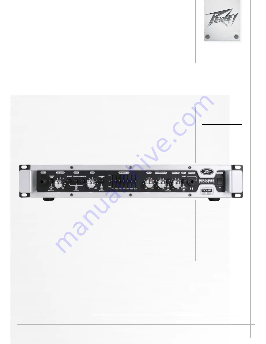
 Headliner

Bass Amplifier Head


Operating

Manual

ENGLISH ............... 15
FRANÇAIS ............ 20
ESPAÑOL .............. 24 
DEUTSCH .............. 28
ITALIANO .............. 32
PORTUGUÊS ........ 36

中文

 ...................... 40

日本語

 .................. 44

Summary of Contents for Headliner

Page 1: ...www peavey com Tour Series Headliner Bass Amplifier Head Operating Manual ENGLISH 15 FRANÇAIS 20 ESPAÑOL 24 DEUTSCH 28 ITALIANO 32 PORTUGUÊS 36 中文 40 日本語 44 ...

Page 2: ...ivement le guide fonctionnant pour avertissements supplémentaires Är avsedd att varna användaren för förekomsten av oisolerad farlig spänning inom produktens hölje som kan vara av tillräcklig nivå för att personer ska riskera elektrisk stöt Är avsedd att uppmärksamma användaren på förekomsten av viktiga handhavande och underhållsinstruktioner service i den litteratur som medföljer produkten OBSERV...

Page 3: ...ack rear support should be provided 17 Note for UK only If the colors of the wires in the mains lead of this unit do not correspond with the terminals in your plug proceed as follows a The wire that is colored green and yellow must be connected to the terminal that is marked by the letter E the earth symbol colored green or colored green and yellow b The wire that is colored blue must be connected...

Page 4: ...ter volume and headphone out The Compressor and Crunch features are footswitch selectable The Headliner features a built in XLR direct interface that players can use to route the signal to the house sound system or recording device and an active passive pickup switch that compensates for hot inputs Peavey s exclusive DDT speaker protection circuitry senses the onset of clipping and responds with s...

Page 5: ... turning the tweeter off on your cabinet will result in a more authentic overdriven tone LOW This knob provides a shelving tone control for low frequencies and provides cut boost of 15 dB The center point is flat The center frequency is 50 Hz The 3 dB shelf corner frequency is 100Hz EQ BYPASS This button removes the graphic equalizer from the audio chain When this switch is in the Bypass position ...

Page 6: ...fy that they are not exceeding the 4 ohm load limit and that the cooling vents are free from obstruction The other fault condition is when the output short protection is activated either by a shorted speaker cable or by exceeding the 4 ohm load limit If the LED stays red all the time the amplifier needs to be taken to an authorized Peavey service center immediately for service POWER SWITCH To appl...

Page 7: ...nit as a slave power amplifier the Return Jack should be used as the input DIRECT INTERFACE DI This built in balanced Direct Interface is used to send a buffered signal to an external mixer DI PRE POST SWITCH This button toggles the DI output from pre EQ to post EQ GROUND LIFT This button is provided to prevent a ground loop that may result in hum noise When depressed IN position Ground Lift is en...

Page 8: ...S 4 ohms 300 watts 34 6VRMS Headphone Amplifier Specifications Stereo 8 ohm minimum load Power Output All measurements with no more than 1 THD N 8 ohms 250 mW 1 41VRMS x 2 Preamplifier Specifications Settings for the Following Measurements unless stated otherwise PRE GAIN 5 12 o clock BRIGHT out CONTOUR out CRUNCH out LOW 0 12 o clock HIGH 0 12 o clock GRAPHIC EQ All sliders set to center GRAPHIC ...

Page 9: ...48 NOTES ...

Page 10: ...9 Features and specifications subject to change without notice Peavey Electronics Corporation 5022 Hartley Peavey Drive Meridian MS 39305 601 483 5365 FAX 601 486 1278 www peavey com 2011 EX000129 NOTES ...

Page 11: ...return shipping charges How To Get Warranty Service 1 Take the defective item and your sales receipt or other proof of date of purchase to your Authorized Peavey Dealer or Authorized Peavey Service Center OR 2 Ship the defective item prepaid to Peavey Electronics Corporation International Service Center 412 Highway 11 80 East Meridian MS 39301 Include a detailed description of the problem together...

Page 12: ...ective 2002 96 EC Annex IV OJ L 37 38 13 02 03 and defined in EN 50419 2005 The bar is the symbol for marking of new waste and is applied only to equipment manufactured after 13 August 2005 U S customer warranty registration ...

Page 13: ......

Reviews: