background image

Rear Panel

Loudspeaker System Specifications 

_ PAGE _1_ 

The 

XS™12 Sub 

speaker system power amplifier providing the power is a low-

distortion reliable fan-cooled unit providing a total of 1,000W peak available 

power for the system.  The power supply for the power amp is a switch mode 

type for low weight and high efficiency.  The amplifier features DSP processing 

for the crossover functions, compression and limiting, and the low-frequency EQ. 


Input is via a combo female XLR and 1/4” TRS phone jack with balanced input to 

the preamp/EQ electronics, and a gain control.   

A pair of High-Pass Outputs in the form of male XLR jacks provides a buffered 

and balanced output signal for satellite speakers to carry the high range of the 

music.  A Full-Range Thru output has a male XLR connector.  These outputs 

allow linking of additional speaker systems, or feed of the signal to other devices, 

etc.   


Applications 

The Peavey 

XS™12 Sub 

has a variety of applications such as extending the 

bass performance of smaller full-range speaker systems for sound 

reinforcement, public address, side fill system, karaoke or musical playback.  

A typical signal source for the line-level inputs of the Peavey 

XS™12 Sub 

would 

be a sound reinforcement mixing console (mixer) or the output from a CD player, 

MP3 player or tape deck.  The high-pass filtered signal from the 

XS™12 Sub 

would then be sent to a full-range powered speaker system, easing the burden of 

deep bass from this speaker system.   


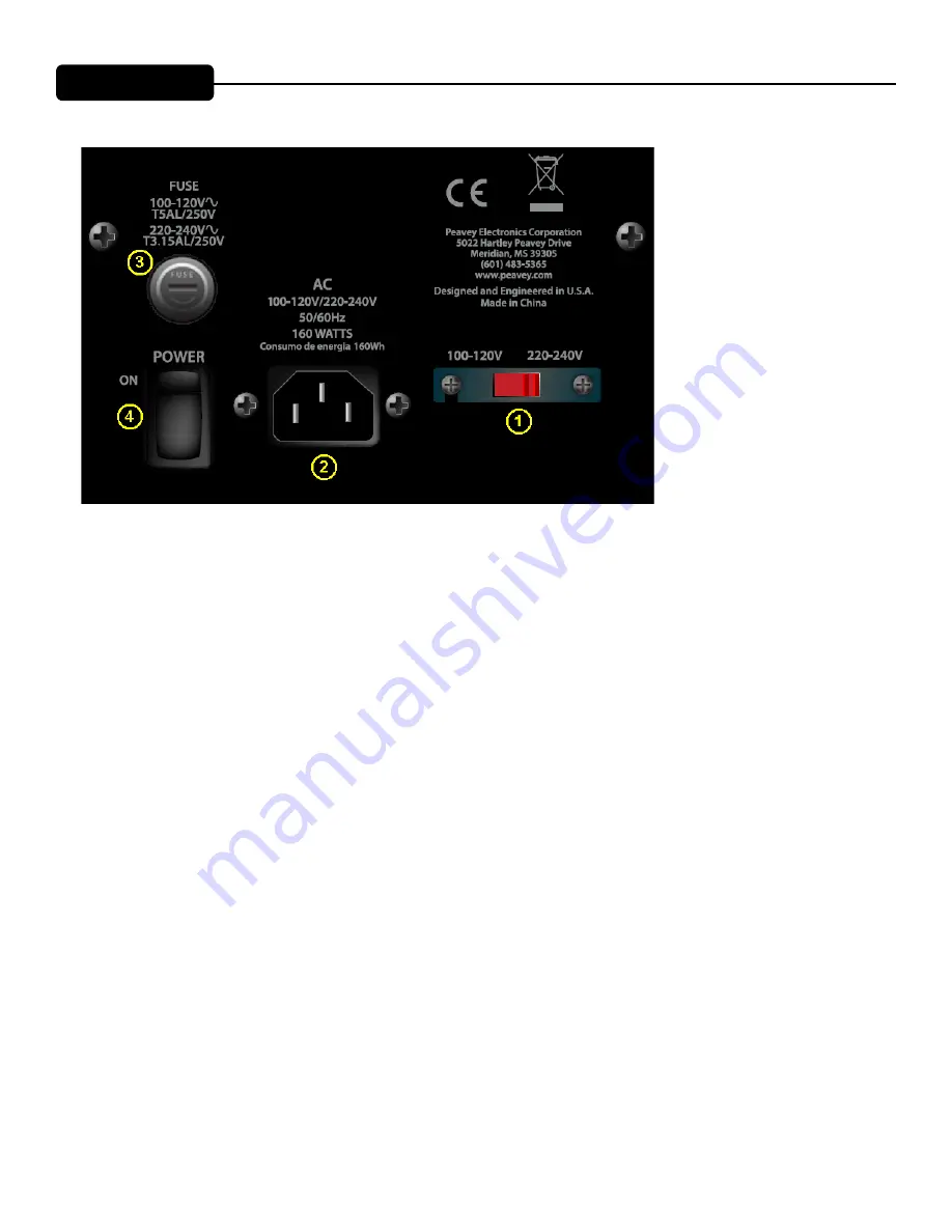
REAR PANEL 


BOTTOM 


 VOLTAGE SELECTOR SWITCH (1)

The AQ™12 has a voltage selector switch to allow switching between an input power voltage of 120VAC to a 

range from 220VAC to 240VAC, all at either 50 or 60 cycles per second (Hz).  It should be set to the proper volt-

age for your country out of the box.  However, world conditions are such that some areas have power line voltag-

es differing from the voltage used by the majority of any given locale.  

Be sure to check the position of the voltage selector switch to see that it matches the power line voltage used 

locally.  If it does not match, then to change the voltage to the correct one, follow the steps outlined below.

Changing the Voltage Range of the AQ™12

First, make sure the AQ™12 is disconnected from the power line, and that the power switch (3) is in the OFF 

position.

Second, unscrew the screws holding the clear switch protector on the voltage selector switch (1) just a little, just 

enough to allow rotation of the clear switch protector.  The screws DO NOT need to be unscrewed very far.

Third, rotate the clear plastic protector about 90 degrees to uncover the voltage selector switch.  One side of the 

cover has a slot, the other just a hole, the side with the hole is the side that pivots.

Fourth, using a small flat blade screwdriver, push the red selector switch slide plate to the other side from where 

it was.   The voltage that is now visible on the red slide plate is the one you have selected.

Fifth, rotate the clear plastic protector back underneath the loosened screws, and tighten one down while hold-

ing the clear plastic protector in place.  Tighten the other screw down, and make sure both screws are tight.

If the screws are over-tightened, this could damage the voltage selector switch clear plastic cover, so do not apply 

excessive force to the screws!

The IEC power cord that is correct for your locale can now be plugged into the IEC receptacle (2), and the Power 

Summary of Contents for AQ 12

Page 1: ...www peavey com AQ 12 Enclosure Operating Manual...

Page 2: ...om that to which the receiver is connected Consult the dealer or an experienced radio TV technician for help The equipment complies with FCC radiation exposure limits set forth for an uncontrolled env...

Page 3: ...c injection molded trapezoidal enclosure Cabinet has dual rear corner angled sides for floor monitor use Full coverage perforated steel grille with powder coat finish Pole mount molded in for 1 3 8 di...

Page 4: ...re is 670W peak available dynamic power for the woofer and 330W peak available dynamic power for the tweeter The power supply for both amps is a switching type for low weight coupled with low cost Bot...

Page 5: ...e power line and that the power switch 3 is in the OFF position Second unscrew the screws holding the clear switch protector on the voltage selector switch 1 just a little just enough to allow rotatio...

Page 6: ...e sure that the mixer and all other associated equip ment are properly grounded IEC POWER CORD CONNECTION 2 This receptacle is for the IEC line cord supplied that provides AC power to the unit It is v...

Page 7: ...k is established BT PAIR LED and button 10 LED illuminates blue when the BT Pair button is pushed and the speaker is paired with another Bluetooth de vice position The ON position is with the top side...

Page 8: ...n a line or to provide a feed to a powered subwoofer or other electronics that needs to receive a full range version of the input signal When the MIX DIR button is engaged in it provides a mixed signa...

Page 9: ...u are using an extension cord or power strip with this powered speaker make sure it is of good quality and of a sufficient current capacity to main tain safety and maximize the power output capability...

Page 10: ...TRS 1 4 phone plug or the XLR plug will pro vide superior interference rejection and performance Sometimes with difficult interference problems it will be helpful to lift the shield ground Pin 1 of an...

Page 11: ...verable The pairing LED should start blinking 2 Go to your devices Bluetooth screen and select the available Peavey speaker Once paired the pairing LED should light continuously Stereo Linking To link...

Page 12: ...al voice bandwidth to reduce booming or sibilance and provides a mild presence boost to help with intelligibility ACOUSTIC Preset This Preset provides a nominally flat frequency response within the li...

Page 13: ...If speaker cables with 1 4 plugs are used as input cables instead of shielded cables they will be prone to hum or buzz Hum may be ground loop related It may be helpful to lift the shield ground Pin 1...

Page 14: ...use gloves to apply a plastic finish protector such as Armor All protectant or a similar product to the surface of the plastic cabinet only Note that the cabinet will be slippery after these treatment...

Page 15: ...bass boost subsonic filtering and overall response shaping and the high frequencies shall be equalized for response shaping The enclosure shall be constructed of injection molded plastic with a UL fla...

Page 16: ...l Electronic DSP based two way crossover with driver EQ level matching bass boost limiting and sub sonic filtering Crossover Slopes Linkwitz Riley 24 dB octave 4th order low pass 24dB octave fourth or...

Page 17: ...wer Sine Wave Power 240 watts less than 1 distortion Tweeter 330 watts peak dynamic power Sine Wave Power 120 watts less than 1 distortion Before DSP compression and limiting engages Electronic Input...

Page 18: ......

Page 19: ......

Page 20: ...d only to equipment manufactured after 13 August 2005 www peavey com Warranty registration and information for U S customers available online at www peavey com warranty or use the QR tag below Feature...

Reviews: