background image

54

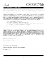
  DECLARATIONS OF CONFORMITY 

FCC Compliance Federal Communications Commission United States Class B Manual Statement This equipment 
has been tested and found to comply with  the limits for a Class B digital device, pursuant to part 15 Section 
15.107  & 15.109 of the FCC Rules. 

These limits are designed to provide reasonable protection against harmful interference in a residential 
installation. This equipment generates, uses and can radiate radio frequency energy and, if not installed and 
used in accordance with the instructions, may cause harmful interference to radio communications. However, 
there is no guarantee that interference will not occur in a particular installation. If this equipment does cause 
harmful interference to radio or television reception, which can be determined by turning the equipment off and 
on, the user is encouraged to try to correct the interference by one or more of the following measures: 


• Reorient or relocate the receiving antenna. 


• Increase the separation between the equipment and receiver. 


• Connect the equipment into an outlet on a circuit different from that to which the receiver is connected.   


• Consult the dealer or an experienced radio/TV technician for help. 

European Commission Compliance 

We hereby declare under our sole responsibility that the product herein identified, to which this declaration 
relates,  is  in  conformity  with  the  essential  requirements  and  other  relevant  requirements  of  the  European 
Parliament,  European  Council,  and  meets  all  requirements  of  the  Canadian  Interference-Causing  Equipment 
Regulations. (Cet appareil numérique de la classe B respecte toutes lecs exigences du Règlement sur le matérial 
brouilleur du Canada), : EN 55032(2012)+AC1, EN 61000-3-2 (2014), EN 61000-3-3 (2013) and EN 55103-2 (2009) KN 
32 (2015) and KN 35 (2015) In accordance with RRA Notice 2016-24(2016. 12. 07) RRA Notice 2016-26(2016. 12. 19) 
RRA Notice 2016-79(2016. 12. 19) VCCI CISPR 32 (2016) 

KC & PSE certifications are pending 
 
Trade Name: PEARL Corporation 

Model: Mimic Pro 
 
Description: Electronic Drum Module 

Information is contained in a report by: CKC Laboratories, Inc 

Dated: May 3, 2017 

Summary of Contents for MIMP24B

Page 1: ...ELECTRONIC DRUM MODULE USER MANUAL VER 1 01 MIMP24B...

Page 2: ...electronic drum sound module For the first time in electronic drums the module has full resolution multi microphone and 24 bit samples Adjustable routing to the 16 outputs allows for incredible flexi...

Page 3: ...nsmitters etc as well as high power wireless hardware Make sure to turn off the power before making any connections Never switch off Mimic Pro immediately after an operation is finished such as copyin...

Page 4: ...ign Triggering Settings Zone Volume Triggering Settings Curves MIDI Triggering Settings Crosstalk Suppression and Ride Split Setting Up a Pad with the Mimic Pro Preset Trigger List Steps to Setup a Ne...

Page 5: ...nsion MIDI IN OUT Use a standard five pin MIDI cable to transfer MIDI data to and from an external MIDI source LINE OUT 1 6 Six balanced TRS outputs HEADPHONE JACK Connection for a pair of stereo head...

Page 6: ...nsion Local AC Voltage 90 230v AC Voltage DC Voltage Trigger Pads or electronic trigger signals MIDI Enabled equipment Analog Audio Signal Outputs 16x Analog Trigger Signal 16x MIDI I O AC DC Converte...

Page 7: ...window displays the name of the kit that is currently selected KIT SCROLL WINDOW Navigate forward and backward through Mimic Pro s kits SETLIST MAIN KIT LIST Build a setlist of kits in performance seq...

Page 8: ...controlled digitally via the encoder touchscreen ii Be sure to lower the volume before you start playing and slowly raise to a comfortable level iii The headphone output has it s own mixer where each...

Page 9: ...re are also areas on Mimic Pro s user interface that accept a double tap On the Home Screen double tap on the Kit Display Window the grey bar see Pic 3 between the headphones fader and Home button wil...

Page 10: ...ata Wheel to load the chosen kit preset If you double tap on a fader a red blinking frame around the fader will appear see Pic 5 This means that the fader is in Edit Mode and can be adjusted using the...

Page 11: ...nd cymbals connect via a single TRS cable except Hi Hat and many Ride cymbals there are some ride cymbals on the market that use single cable connection Hi Hat uses two cables because it has a pad jac...

Page 12: ...12 QUICK START GETTING STARTED QUICK START Quick Start guide fastest way to get playing Does NOT include advanced pad setup https youtu be 7wLHPdlwkRs Pic 8 Quick Start 1 Pic 9 Quick Start 2...

Page 13: ...Data Wheel Double tap on the top bar to open the Kit Loading menu and load the first Kit Preset in the list by selecting it and pressing the Load button Press the Trigger window drum sticks and gear i...

Page 14: ...re almost set after selecting the right pad presets The only things left to do after setting the pad presets are calibrating the Hi Hat pad and adjusting dynamics to your taste Pic 11 Triggering Sett...

Page 15: ...settings window Pic 13 Then proceed to TRIGGER HH Control HH Pos tab to calibrate your Hi Hat Pic 15 Make sure that your Hi Hat is in the fully open position If a controller is built into the pedal fu...

Page 16: ...ould playing a tight Hi Hat With a fully closed Hi Hat adjust the Max Close fader so it would be right on top of grey bar It is the blue strip in Pic 18 Pic 18 Hi Hat Max Close Level Setup Step three...

Page 17: ...and you re finished calibrating the Hi Hat the next step would be adjusting the dynamics CALIBRATING THE HI HAT continued Note Some Hi Hats for instance Pearl E Pro EHH 2 may work better if you apply...

Page 18: ...lues will be your best option and the feel would be natural On the High settings it will be easier to play but the natural feel will decrease Close to Open Pedal Travel adjusts the release of the peda...

Page 19: ...Velocity adjustment is available for each zone of the connected drum pad If you have great response on the Center zone of your snare drum pad but you have to hit the Rim zone really hard to get the ne...

Page 20: ...ay cause misfires For instance if you hear random ghost notes triggering on the snare tom or any other drum input this means that there is some audio signal hum noise going to that trigger input You c...

Page 21: ...range of rim articulation rim click or sidestick with the ability to play rimshots There are a few steps to setup the Rimshot Threshold on such drum pads After these two steps are completed you should...

Page 22: ...it s 3 ms By setting it lower on all pads you can make latency lower but it actually won t be noticeable While the quality of triggering may become worse if you set it really low the triggering engine...

Page 23: ...nd 6 10 ms HEAD RIM BALANCE setting doesn t appear on every pad Only on pads with two piezos like mesh head pads With this setting you can adjust the balance in triggering between the head and rim zon...

Page 24: ...iculation On all other trigger inputs there are no layers so there are many options for creating unique hybrid kits For instance you can put any sounds you want clap tambourine cowbell on tom rims Sin...

Page 25: ...eparate sensitivity and amp adjustment in Advanced Triggering Settings The only way to adjust the dynamics before Velocity Amp is using the Top Velocity fader Adjust the Top Velocity fader down but do...

Page 26: ...in terms of velocity layer but they will sound quieter Velocity Curve adjusts velocities velocity layers to your playing style If you drag the dot in left bottom corner up this will make soft hits on...

Page 27: ...t them at the same time but the tom hit was 1 ms earlier than the crash hit and the tom hit triggered the cymbal crosstalk this means that your actual hit on cymbal may not be triggered Remember it ju...

Page 28: ...if needed If you feel like the setting is way off too much adjustment needed in Top Velocity or Velocity Amp and the performance is lacking then go to section called Steps to Set Up a New Pad not on...

Page 29: ...r x0 7 If you feel like there is not enough sensitivity and you need to hit really hard to get the desired velocity then probably you need higher Sensitivity and Amplify settings Try to increase the S...

Page 30: ...ng them to different pad zones in the Triggering Settings Kit Instruments Assign tab For instance you can load claps tambourines or even small parts of your tracks and assign them to the tom s rims It...

Page 31: ...t name experiment with settings or change any instrument If you press NO then a new empty kit will be created All cells will be empty FXs and mix balance will be reset This is the correct way to creat...

Page 32: ...i Hats may take 1 2 seconds to load Tap the cell again to audition the loaded instrument This makes it easy to decide which instrument to load in your kit preset Make note that cells have to be popula...

Page 33: ...your choice simply touch the desired tab to see the respective menu Once the tab is activated it will light up Example PHONES MIX To access the Mixer menu start from the Home Screen then press on the...

Page 34: ...lue faders Pic 44 Master Mix Master mix section has green faders Reverb and Master faders have dark rose color in both mixers EXCEPTION The ride and Hi Hat cymbals use direct microphones and may also...

Page 35: ...et used the level you send him is constant To adjust the volume fader of any channel simply use your finger to move the fader up or down For finer incremental adjustments the Data Wheel works best To...

Page 36: ...the Reverb effect by changing the settings in the FX menu This combination offers a lot of creative possibilities In addition the sound of Reverb will also vary depending on the mics it is applied to...

Page 37: ...e end of the sample Basically it s a fade out for the sample The longer release the longer the fade out will be It works great for taming the tails of samples If you want to make a short pop or funk s...

Page 38: ...pplied The COMP reduces the level of an audio signal if its amplitude exceeds a certain threshold It is commonly set in decibels dB where a lower threshold for instance 30 dB means a larger portion of...

Page 39: ...hanges Everything described above may be difficult to understand if youhaveneverusedaCompressor Tohelpwithunderstanding below are some typical steps to setup COMP FX ADJUSTMENTS WORKING IN KIT PRESETS...

Page 40: ...me time To adjust the band tap on the band point and drag it on the EQ display To reset the band tap and hold on the Hold to Reset button on the top of EQ display Bands 1 and 5 are shelf filter types...

Page 41: ...onds directly to the adjacent mic channel Now you should have instruments sent to Reverb Play them to check to ensure you can hear reverb applied Be sure to also check that the Reverb fader of the Mix...

Page 42: ...igh frequencies and hyped low frequencies The Comp compression is useful for making slight or significant depending on settings changes to the dynamics of the sound coming out of the headphones output...

Page 43: ...lso perform this function To change the tempo BPM press or press and hold the to increase or decrease the beats per minute To change the time signature press or press and hold the to increase or decre...

Page 44: ...te or deactivate the tempo SETLIST Begin by selecting the New Setlist box You will be given an option to Clone Current Setlist select Yes or No Select No to create a new Setlist then name and enter yo...

Page 45: ...h WAV files and turn Mimic ON On the Home Screen double tap the Playlist window to open the Playlist menu The Playlist menu features the Play pause Previous and Next controls for your tracks After son...

Page 46: ...etup Buttons on the right side are a bit different from others Their functions are enabled by holding the button down and turning the data wheel while holding LOOP START sets the position of the loop...

Page 47: ...t Wave Files from USB Stick lets you import your WAV files and use them as instruments WAVs must be 16 bit or 24 bit and have 44100 Hz sample rate Export Mimic Config to USB Stick saves the Mimic Pro...

Page 48: ...UX can be kick tom or cymbals so you don t have to memorize it when you are setting up routing On the right side you can select the Output It can be mono or stereo If you are routing a signal that is...

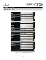
Page 49: ...49 SETTINGS continued ROUTING FULL VIEW Pic 61 Full view of Complete Routing Screen...

Page 50: ...50 SETTINGS continued ROUTING FULL VIEW Pic 61 Full view of Complete Routing Screen continued...

Page 51: ...Pro after resetting On this tab you can reset Mimic Pro to the factory settings and apply software updates The button labeled Apply Software Update lets you update Mimic Pro s software Detailed instru...

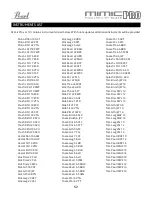
Page 52: ...RFP Kick Pearl 22 SFT Kick Pearl 22 WRH Kick Pearl 22 WRS Kick Snr 22 PLS Kick Snr 22 SQB Kick Tma 24 SCM Kick Yha 22 HRD Kick Yha 22 SFT Ride Pst 22 PWR Ride Sbn 20 AAE Ride Sbn 21 PTR Ride Slt 21 CS...

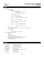
Page 53: ...DC converter 100V 240V AC 50 60 Hz 4 DC Requirements a 12 VDC b 3A c 2 1mm Center Positive Coaxial DC plug ii Mechanical Dimensions Weight 1 Width 12 5 2 Height 6 5 3 Depth Chassis Only 2 75 4 Depth...

Page 54: ...eiving antenna Increase the separation between the equipment and receiver Connect the equipment into an outlet on a circuit different from that to which the receiver is connected Consult the dealer or...

Reviews: