background image


Your Source for Healthcare and 
Wellness Infotainment


MODEL NUMBER:


PDI-E42LEDA-NK LED TV 

Document Number:


PD196-278R3 


Service Manual 

Page 7 of 11 


PDi Communication Systems, Inc.   40 Greenwood Lane   Springboro, Ohio 45066 USA   PH 1-800-628-9870  FX 937-743-5664  


Speakers 

The speakers 

PD164-048

 are held in place by 2 screws each as shown. 


Board Removal 

1.  The main board 

PD128-1756

 is secured with 3 screws. 

2.  The pillow speaker board 

PD128-1752

 is secured with 2 screws. 

3.  The power board 

PD128-1779

 is secured with 4 screws. 

4.  The LED driver board 

PD128-1780

 is secured with 4 screws. 

5.  The IR board 

PD128-1783

 is secured with plastic tabs. 

6.  The TCON board 

PD128-1782

 is secured with 4 screws. 

7.  The keypad board (page 7,  #5) 

PD128-1774

 is secured with 2 

screws.


Summary of Contents for PDI-E42LEDA

Page 1: ...PDI E42LEDA Modular High Definition Healthcare grade LED Television Document Number PD196 278R3 ...

Page 2: ...oro Ohio 45066 USA PH 1 800 628 9870 FX 937 743 5664 Table of Contents Copyright Disclaimer and Trademarks 3 Regulatory Information 4 Product Safety Servicing Precautions 4 PDI E42LEDA NK Specifications 5 Disinfecting and Cleaning 6 Checking Points to Consider 6 Product Identification 6 Back Cover 6 Speakers 7 Board Removal 7 Parts List 8 Basic Troubleshooting Steps 9 Reassembly 10 Safety Checks 1...

Page 3: ...aimer and Trademarks Copyright PDi Communication Systems Inc claims proprietary right to the material disclosed in this service manual This manual is issued in confidence for servicing information only and may not be used to manufacture anything shown herein Copyright 2014 by PDi Communication Systems Inc All rights reserved Disclaimer The author and publisher have used their best efforts in prepa...

Page 4: ...mmunication Systems Inc has determined that in the as shipped factory default condition this healthcare television product meets the energy efficiency guidelines Changes to the default as shipped television configuration and settings such as enabling certain optional features and functionalities may increase energy consumption beyond the limits required for ENERGY STAR qualification ENERGY STAR is...

Page 5: ... Min Max Volume Limiter Yes Start Power on Volume Yes Selectable Pillow Speaker 12VDC 5VDC OFF 5VDC Universal Pillow Speaker Recognition Yes Auto Power On Yes Channel Enable Disable Yes Bed A B C D Yes Programmable Source Selection Yes Direct Access to Source from Pillow Speaker Yes Progressive Scan Yes Parental Control V CHIP Yes USB Clone Programmable Yes 2D Digital Comb Filter Yes Sleep Timer Y...

Page 6: ...for the cleaning of the LCD screen Checking Points to Consider Dynamic picture adjustments to Brightness Contrast Color and Tint are available using the IR Remote Control Part number PD108 420 using the SETUP Picture menu 1 Check the appearance of the replacement panel and circuit boards for both physical damage and part number accuracy 2 Check the model label Verify model names and board model ma...

Page 7: ...164 048 are held in place by 2 screws each as shown Board Removal 1 The main board PD128 1756 is secured with 3 screws 2 The pillow speaker board PD128 1752 is secured with 2 screws 3 The power board PD128 1779 is secured with 4 screws 4 The LED driver board PD128 1780 is secured with 4 screws 5 The IR board PD128 1783 is secured with plastic tabs 6 The TCON board PD128 1782 is secured with 4 scre...

Page 8: ... BD 2 PD128 1752 PILLOW SPEAKER BD 3 PD128 1779 POWER SUPPLY BD 4 PD128 1780 LED DRIVER BD 5 PD128 1774 KEYPAD BD 6 PD134 244 KEYPAD 7 PD133 933 BACK CABINET 8 PD289 143 32 ASSEMBLY LCD PANEL 9 PD180 017 RF I O FRAME 10 PD180 018 PILLOW SPEAKER I O FRAME 11 PD164 048 SPEAKERS 12 PD106 798 LVDS CABLE 13 PD106 804 IR KEYPAD CABLE 14 PD128 1783 IR BOARD 15 PD106 801 P101 to LED POWER CABLE 16 PD106 8...

Page 9: ...R Perform Auto Program Replace LVDS cable PD106 798 Replace main board PD128 1756 Replace panel PD289 143 Verify TV is connected to a coax cable that has RF signal Verify channel is programmed into current service level Tune to channel with remote Tune to channel with TV keypad CANNOT TUNE TO A DESIRED CHANNEL Verify correct Signal type is set in Setup Channels menu Verify Channel Memory Override ...

Page 10: ... Replace board LED driver PD128 1780 Replace LVDS cable PD106 798 Replace main board PD128 1756 Replace panel PD289 143 Verify TV is not muted Verify cable is seated into main chassis and into IR board Verify pillow speaker is not being used PICTURE OK NO SPEAKER SOUND Verify TV speaker has not been disabled for the current Service Level in the Sound Internal Speaker Enable menu Replace speaker PD...

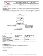
Page 11: ...aced in parallel with this circuit to measure AC rms or DC voltage If leakage currents are greater than the maximum allowed inspect the TV for insulation or component breakdowns The maximum allowed leakage current depends on the type of power the unit receives and whether the unit is within reach of the patient bed chair TV Type Max Leakage Current Max DMM Voltage Reading Footwall TV 120VAC ground...

Reviews: