background image


Safety 

International Safety Symbols 

This symbol, adjacent to another symbol or 
terminal, indicates the user must refer to the 
manual for further information. 


This symbol, adjacent to a terminal, indicates that, 
under normal use, hazardous voltages may be 
present 


Double insulation 


SAFETY NOTES 

  Do not exceed the maximum allowable input range of   

any function 

  Do not apply voltage to meter when resistance function  

is selected. 

  Set the function switch to OFF when the meter is not in 

use. 


WARNINGS


  Set function switch to the appropriate position before  

measuring. 

  When measuring volts do not switch to 


current/resistance modes.


  When changing ranges using the selector switch always 

disconnect the test leads from the circuit under test.


  Do not exceed the maximum rated input limits.


Summary of Contents for CM-220

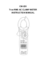
Page 1: ...CM 220 True RMS AC CLAMP METER INSTRUCTION MANUAL...

Page 2: ...TES Do not exceed the maximum allowable input range of any function Do not apply voltage to meter when resistance function is selected Set the function switch to OFF when the meter is not in use WARNI...

Page 3: ...d Remove the battery if the meter is to be stored for long periods Always discharge capacitors and remove power from the device under test before performing Diode Resistance or Continuity tests Voltag...

Page 4: ...lect button 11 LCD display 12 COM input jack 13 V CAP TEMP Hz input jack 14 Battery Cover 1 AC DC AC alternating current and DC direct currrent 2 Minus sign 3 8 8 8 8 6000 count 0 to 5999 measurement...

Page 5: ...5 2 digits 60 00 VDC 600 0 VDC AC Voltage 50 400Hz 6 000 VAC 1 8 8 digits 60 00 VAC 600 0 VAC Resistance 600 0 1 0 4 digits K 1 5 2 digits K K M 2 5 3 digits M 3 5 5 digits Capacitance 40 00nF 4 0 re...

Page 6: ...50 400Hz VAC Operating Temperature 41 to 104 o F 5 to 40 o C Storage Temperature 4 to 140 o F 20 to 60 o C Operating Humidity Max 80 up to 87 F 31 C decreasing linearly to 50 at 104 F 40 C Storage Hu...

Page 7: ...he 1000A or 600A range 2 If the range of the measured is not known select the higher range first then move to the lower range if necessary 3 Press the trigger to open jaw Fully enclose one conductor t...

Page 8: ...jack and the red test lead banana plug into the positive diode jack 2 Turn the rotary dial to the position 3 Press the MODE button until appears in the display 4 Touch the test probes to the diode un...

Page 9: ...uency on the display 7 Press the Hz button again to indicate on the display Read the of duty cycle on the display Temperature Measurements WARNING To avoid electric shock disconnect both test probes f...

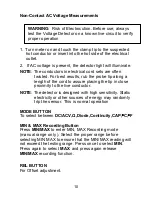
Page 10: ...th high sensitivity Static electricity or other sources of energy may randomly trip the sensor This is normal operation MODE BUTTON To select between DC ACV Diode Continuity CAP C F MIN MAX Recording...

Page 11: ...de and is generally the best mode for most measurements For measurement situations requiring that a range be manually selected perform the following 1 Press the RANGE button The Auto Range display ind...

Page 12: ...either repair or replace the defective unit at PDI s discretion A purchase receipt or other acceptable form of proof of original purchase date will be required before any warranty processes begin PDI...

Page 13: ...13...

Reviews: