PCM FW6 Building Instructions Download Page 14

FW6 Building Instruction                                                                                                                      February 2015 
                                                                                                                        

www.pcm.at                                                                                                                                                            

14 

If you want to make the most beautiful solution, you can lead 
the wire out of the pylon and place the lever right behind. But 
you have to shorten the lever a little for that. 
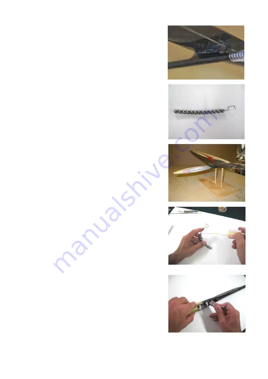
 

8. Ballast: 


As ballast we use lead 

balls

 from the 

fishing shop

. You can 

easily assemble and vary this kind of ballast. 
 
The balls are strung on a 

steel wire of 1,0mm diameter

. Bend 

the end of the wire to a small hook. With this 

hook

 the ballast 

pack can be 

locked

 on the radio board. 

   
To locate the exact position of the ballast inside the fuselage, 
lay the model on a 

device for measuring the centre of gravity


(see picture). Move the ballast until you get the desired centre 
of gravity. 
When bending the wire you should make sure that you 

don’t 

create 180 ° curves

, as the wire may break then. 


Put a drop of thin 

super glue onto


the first and the last lead 

ball

 to fix their position. As you must curve the ball chain for 

threading it into the ballast tube, bend the wire in the desired 
curvature when you glue the balls.  


Insert the ballast through the left opening of the fuselage 

into 

the ballast tube

.  


Summary of Contents for FW6

Page 1: ...FW6 Building Instruction February 2015 www pcm at 1 Wing span mm 1440 Wing area dm2 20 5 Aspect ratio 10 18 Take off weight g ab 240 Airfoil Zone V2 BUILDING INSTRUCTION SAL HLG FW6...

Page 2: ...Push rods for ailerons 6 3 Gluing the radio board 7 Installation of the CFR stabs 7 1 Installation of torsion springs 7 2 Connection of the wires 8 Ballast 9 Battery shape and installation of receiver...

Page 3: ...Servo support Micro ball connectors Building instruction for download from our website 2 What else do you need Epoxy glue for example UHU 300 endfest or Pattex Stabilit Super glue both runny and thic...

Page 4: ...he following when you assemble the model Always use glue sparingly Grind all gluing spots thoroughly before you apply the glue Electronic components should be placed as far as possible to the front as...

Page 5: ...fixing it into the right position a plywood template is enclosed The brass tubes are glued directly to the ailerons Therefore you have to grind the tubes and the ailerons well to guarantee a good glu...

Page 6: ...nce sheets Use them under the tube and in front of the tube to place the tube as high as possible to the upper edge of the aileron Note that there is enough space near the hinge to guarantee the free...

Page 7: ...t 7 5 2 Installation of throwing blade The throwing blade has a molded adhesive flap By this installation is greatly simplified Grind the gluing spots on wing and blade well and free them from sanding...

Page 8: ...radio board slightly If you look in flight direction the upper edge is shifted to the right the lower edge to the left In addition we bend the servo levers easily By this the maximum deflections can...

Page 9: ...too brittle for this small joint may be too brittle At the other end we chose the standard version with 1mm steel hook and securing wire At the other servo connection you can just make an S hook Push...

Page 10: ...d out the optimal position To do so place the radio board inside the fuselage without gluing and mount all servos The front aileron servo should be situated 130 mm from the fuselage tip You can fix th...

Page 11: ...d carbon rovings left and right of the gluing spots for additional strength Best way to apply is together with gluing of the board If you have a hard landing always check if the radio board is still f...

Page 12: ...on see 3 rd picture Rudder for right handers view from above Kevlar wire to the right Cut a slot in the rudder in extension of the axis of the fuselage It is advisable to leave the lower laminate uncu...

Page 13: ...tter bonding with epoxy glues UHU 300 endfest Pattex Stabilit or similar 7 2 Connection of the wires Drill a hole in the boom to lead the wire inside the fuselage to the servo We stick a bowden cable...

Page 14: ...ballast pack can be locked on the radio board To locate the exact position of the ballast inside the fuselage lay the model on a device for measuring the centre of gravity see picture Move the ballast...

Page 15: ...FW6 Building Instruction February 2015 www pcm at 15 The hook of the ballast package is locked in the servo board...

Page 16: ...reat 8 channel 2 4GHz receiver it is also possible to remove the power strip and solder the servos directly to the board This is quite normal with our indoor colleagues To the right a few receivers th...

Page 17: ...rom the leading edge of the wing to the back Expo at app 50 Ailerons measure near fuselage Flaps negative start speed fast thermal search measure near fuselage Flaps positive fast thermal search gentl...

Page 18: ...ap Flap negative for better leveling out of the flight path at the highest point of the launch measure near fuselage Rudder measure at deepest point Set the elevator on 0 at your first flight Don t ma...

Page 19: ...amount of ballast depends of course on the strength of wind and thermals The Zone V2 can tolerate ballast very good and you should not fly with too little weight at higher wind speeds As you can see t...

Page 20: ...aunch from the fuselage No DLG launch at your first flight If there are some wrong settings everything will go too fast at the disc launch to correct these failures by steering 13 Notes for the use To...

Reviews: