


Drawing Number: 21067
Revision: A
PIEZOELECTRIC CHARGE MODE PRESSURE SENSOR GENERAL OPERATION MANUAL
6
4.0
CALIBRATION
These sensors may be calibrated using static hydraulic
techniques, such as dead-weight testers, or by compar-
ison with a reference gage.
When calibrating with a laboratory-style charge
amplifier, set the charge amplifier to LONG, for the time
constant setting, and allow the sensor to stabilize before
applying pressure. If slow drift is apparent, apply the
pressure to the desired level, and immediately take a
reading. Release the pressure and take another reading
at zero pressure to obtain the difference between the
readings at the desired present level and zero pressure.
If the drift is too fast to take a reading, clean the cable
connections according to the procedures out-lined in
Section 7.0, Maintenance.
NOTE: Do not attempt to use a charge amplifier which,
in the long time constant position, has less than a 5 000-
second time constant for quasi-static calibration of
charge sensors. Any drift may cause error.
Several charge amplifiers are designed especially for use
with ceramic sensors, for higher low-frequency
measurements. In general, these types are unsuitable for
calibration of quartz pressure sensors by quasi-static
means.
A factory-supplied, NIST-traceable calibration graph is
provided with each sensor, certifying its charge
sensitivity in pC/psi, or when used with an in-line
voltage amplifier, in mV/psi.
5.0
NORMAL OPERATION
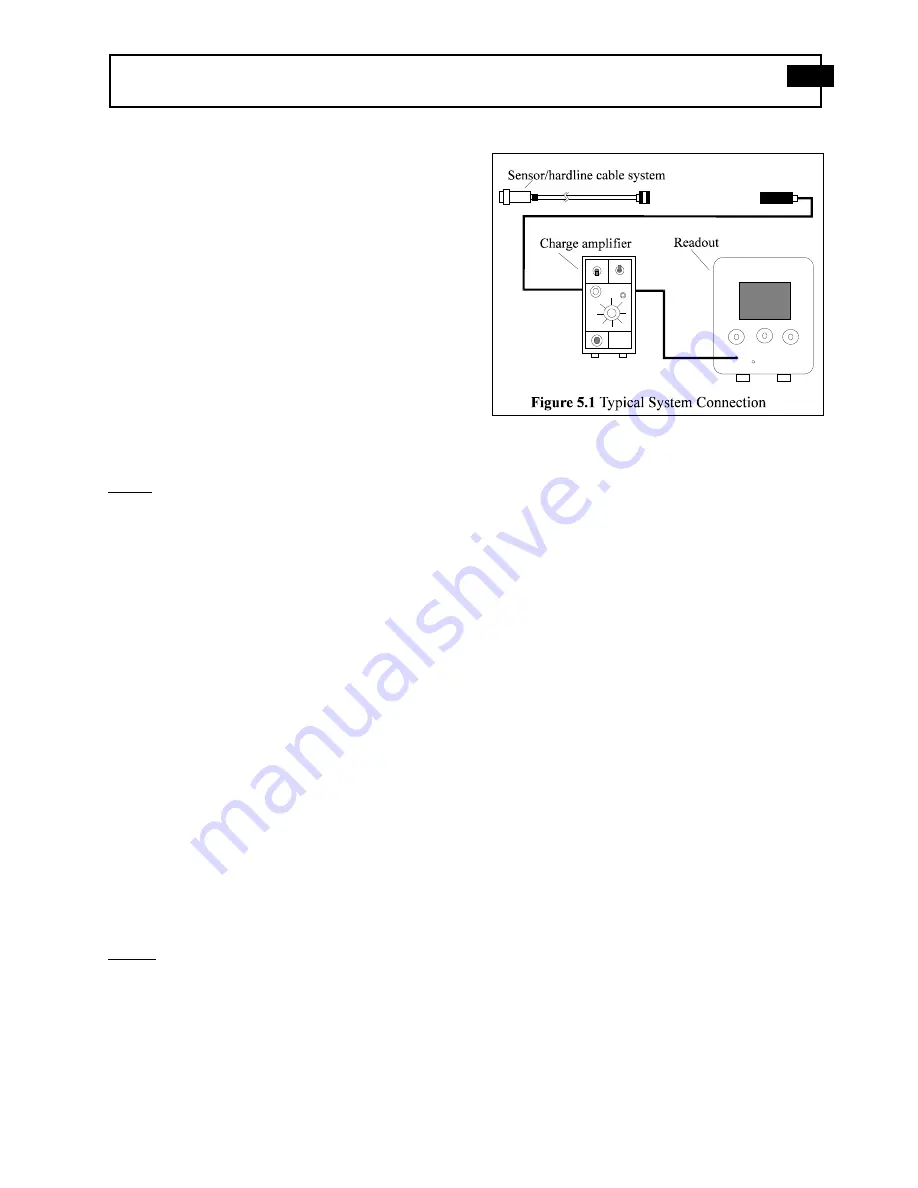
The high impedance signal generated by a charge output
sensor is usually conditioned with a laboratory-style
charge amplifier, such as the PCB Model 462A. The
charge amplifier converts the high-impedance charge
signal generated by the sensor into a low-impedance
voltage signal. This signal may then be transmitted to a
readout or recording device for analysis. See Figure 5.1
for a drawing of a typical system connection.
NOTE: When using charge-amplified systems, the noise
floor of the system is dependent on the input capacitance
to the charge amplifier. To minimize noise, keep the
cable length between the pressure sensor and the charge
amplifier to a minimum. Cable length does not affect
the system sensitivity.
Before connecting the low-noise cable from the pressure
sensor to the charge amplifier, be certain to ground the
charge amplifier. This ensures that any excessive
accumulated static charges across the sensor/cable
combination are harmlessly discharged. If this
precaution is not observed, the input FET of certain
amplifiers may be destroyed. Press the ground button of
the charge amplifier and adjust electrical zero if
necessary.
Once system components are connected, wait a few
minutes for the system to thermally stabilize. Place the
switch in the OPR (operate) position and proceed with
the measurement. Refer to the charge amplifier oper-
ating manual for further operating details.
For fixed sensitivity in-line charge amplifiers, such as
the PCB Series 422, the system sensitivity (mV/psi) is
determined as the product of the charge amplifier
sensitivity (mV/pC) and the sensor sensitivity (pC/psi).
With in-line voltage amplifiers, the system sensitivity is
a function of the sensor, cable, and the in-line voltage
amplifier.
5.1
Polarity
When subjected to increasing pressure, these pressure
sensors have a standard negative-going charge output.
Because most charge amplifiers are signal-inverting, the
resultant signal is positive-going. Reverse-polarity
sensors, for use with non-inverting source follower
amplifiers, are available upon request (“P” option).