


7
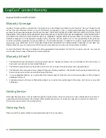
Figure 7: Tee/Supply hose
Figure 8: Spray hose installation
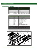
Assembly Instructions
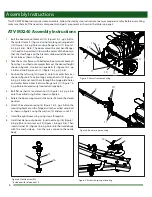
9. Connect the hose coming from the controls to the tee on the
center frame as shown in figure 7. Slide a loose hose clamp
(6) (Figure 1 & 7, pg 5 & 7) onto the hose coming from the
controls. Push the hose onto the tee on the center frame.
Tighten the hose clamp around the hose and tee.
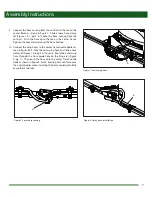
10. Connect the wing hoses to the center frame nozzle bodies as
seen in figure 8 & 9. Take the outer wing hose and slide a hose
clamp (6) (Figure 1 & 8, pg 5 & 7) onto it. Route the outer wing
hose through the hose guide hole on the hinge (a) (Figure
9, pg 7). Then push the hose onto the center frame nozzle
body as shown in figure 8. Note: Exerting to much force onto
the nozzle bodies when installing the hoses could potentially
cause them to break.
6
6
Figure 9: Spray hose routing
a


