


81
2.
Two--Stage Thermostat and Two--Stage Heating
See
Fig. 38 and 39 for thermostat connections)
NOTE
: In this mode the LHT must be ON to select the low--heat
only operation mode in response to closing the thermostat
R--to--W1 circuit. Closing the thermostat R--to--W1--and--W2
circuits always causes high--heat operation, regardless of the setting
of the low--heat--only switch.
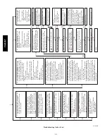
The wall thermostat “calls for heat”, closing the R--to--W1 circuit
for low--heat or closing the R--to--W1 and--W2 circuits for
high--heat. The furnace control performs a self--check, verifies the
low--heat and high--heat pressure switch contacts LPS and HPS are
open, and starts the inducer motor IDM in high--speed.
The start up and shut down functions and delays described in item
1. above apply to the 2--stage heating mode as well, except for
switching from low-- to high--heat and vice versa.
a.
Switching from Low-- to High--Heat
--If the thermostat
R--to-- W1 circuit is closed and the R--to--W2 circuit closes,
the furnace control CPU will switch the inducer motor
IDM speed from low to high. The high--heat pressure
switch relay HPSR is de--energized to close the NC contact.
When sufficient pressure is available the high--heat pres-
sure switch HPS closes, and the high--heat gas valve sole-
noid GV--HI is energized. The blower motor BLWM will
switch to HI HEAT speed five sec after the R--to--W2 cir-
cuit closes.
b.
Switching from High-- to Low--Heat
--If the thermostat
R--to--W2 circuit opens, and the R--to--W1 circuit remains
closed, the furnace control CPU will switch the inducer
motor IDM speed from high to low. The high--heat pres-
sure switch relay HPSR is energized to open the NC contact
and de--energize the high--heat gas valve solenoid GV--HI.
When the inducer motor IDM reduces pressure sufficient-
ly, the high--heat pressure switch HPS will open. The gas
valve solenoid GV--M will remain energized as long as the
low--heat pressure switch LPS remains closed. The blower
motor BLWM will switch to LO HEAT speed five sec after
the R--to--W2 circuit opens.
3.
Cooling Mode--
The thermostat “calls for cooling.”
a.
Single--Speed Cooling
--
See Fig. 38 and 39 for thermostat connections)
The thermostat closes the R--to--G--and--Y circuits. The
R--to-- Y circuit starts the outdoor unit, and the R--to--
G--and--Y/Y2 circuits start the furnace blower motor
BLWM on COOL speed.
The electronic air cleaner terminal EAC--1 is energized
with 115 vac when the blower motor BLWM is operating.
When the thermostat is satisfied, the R--to--G and--Y cir-
cuits are opened. The outdoor unit will stop, and the fur-
nace blower motor BLWM will continue operating on the
COOL speed for an additional 90 sec. Jumper Y/Y2 to
DHUM to reduce the cooling off--delay to 5 sec. See Fig.
38.
b.
Single--Stage Thermostat and Two--Speed Cooling
(Adaptive Mode)
See Fig. 38 and 39 for thermostat connections)
This furnace can operate a two--speed cooling unit with a
single--stage thermostat because the furnace control CPU
includes a programmed adaptive sequence of controlled
operation, which selects low--cooling or high--cooling op-
eration. This selection is based upon the stored history of
the length of previous cooling period of the single--stage
thermostat.
NOTE
: The air conditioning relay disable jumper ACRDJ must
be connected to enable the adaptive cooling mode in response to a
call for cooling. See Fig. 38. When ACRDJ is in place, the furnace
control CPU can turn on the air conditioning relay ACR to
energize the Y/Y2 terminal and switch the outdoor unit to
high--cooling.
The furnace control CPU can start up the cooling unit in either
low-- or high--cooling. If starting up in low--cooling, the furnace
control CPU determines the low--cooling on--time (from 0 to 20
minutes) which is permitted before switching to high--cooling. If
the power is interrupted, the stored history is erased and the furnace
control CPU will select low--cooling for up to 20 minutes and then
energize the air conditioning relay ACR to energize the Y/Y2
terminal and switch the outdoor unit to high--cooling, as long as
the thermostat continues to call for cooling. Subsequent selection is
based on stored history of the thermostat cycle times. The wall
thermostat “calls for cooling”, closing the R--to--G--and--Y circuits.
The R--to--Y1 circuit starts the outdoor unit on low--cooling speed,
and the R--to--G--and--Y1 circuits starts the furnace blower motor
BLWM at low--cool speed (same speed as LO HEAT).
If the furnace control CPU switches from low--cooling to
high--cooling, the furnace control CPU will energize the air
conditioning relay ACR. When the air conditioning relay ACR is
energized the R--to--Y1--and--Y2 circuits switch the outdoor unit to
high--cooling speed, and the R--to--G--and--Y1--and--Y/Y2 circuits
switch the furnace blower motor BLWM to COOL speed.
NOTE
: When transitioning from low--cooling to high--cooling the
outdoor unit compressor will shut down for 1 minute while the
BLWM continues to run at low--cool speed (same speed as
LO--HEAT) until the outdoor unit compressor comes back on at
high speed.
The electronic air cleaner terminal EAC--1 is energized with 115
vac whenever the blower motor BLWM is operating. When the
thermostat is satisfied, the R--to--G--and--Y circuit are opened. The
outdoor unit stops, and the furnace blower BLWM and electronic
air cleaner terminal EAC--1 will remain energized for an additional
90 sec. Jumper Y1 to DHUM to reduce the cooling off--delay to 5
sec. See Fig. 38.
c.
Two--Stage Thermostat and Two--Speed Cooling
See
Fig. 38 and 39 for thermostat connections.
NOTE
: The air conditioning relay disable jumper ACRDJ must
be disconnected to allow thermostat control of the outdoor unit
staging. See Fig. 38.
The thermostat closes the R--to--G--and--Y1 circuits for
low--cooling or closes the R--to--G--and--Y1--and--Y2 circuits for
high--cooling. The R--to--Y1 circuit starts the outdoor unit on
low--cooling speed, and the R--to--G--and--Y1 circuit starts the
furnace blower motor BLWM on low--cool speed (same speed as
LO HEAT). The R--to--Y1--and--Y2 circuits start the outdoor unit
on high--cooling speed, and the R--to--G--and-- Y/Y2 circuits start
the furnace blower motor BLWM on COOL speed. The electronic
air cleaner terminal EAC--1 is energized with 115 vac whenever the
blower motor BLWM is operating. When the thermostat is
satisfied, the R--to--G--and--Y1 or R--to--G--and--Y1--and--Y2
circuits are opened. The outdoor unit stops, and the furnace blower
BLWM and electronic air cleaner terminal EAC--1 will remain
energized for an additional 90 sec. Jumper Y1 to DHUM to reduce
the cooling off--delay to 5 sec. See Fig. 38.
4.
Dehumidification Mode
See Fig. 38 and 39 for Thermidistat connections.
The dehumidification output, D or DHUM on the Ther-
midistat should be connected to the furnace control thermo-
stat terminal DHUM. The dehumidification output, D or
DHUM from a thermostat. When there is a dehumidify de-
mand, the DHUM input is activated, which means 24 vac
signal is removed from the DHUM input terminal. In other
words, the DHUM input logic is reversed. The DHUM in-
put is turned ON when no dehumidify demand exists. Once
24 vac is detected by the furnace control on the DHUM in-
put, the furnace control dehumidification capability is acti-
vated. If the DHUM input is low for more than 48 hours,
the furnace control reverts back to non--Thermidistat mode.
PG95X
AT